EasyManua.ls Logo

Mitsubishi GOT1000 Series - Page 952

Mitsubishi GOT1000 Series
1216 pages
To Next Page IconTo Next Page
To Previous Page IconTo Previous Page
Loading...
23 - 10
23.2 Connection Cable
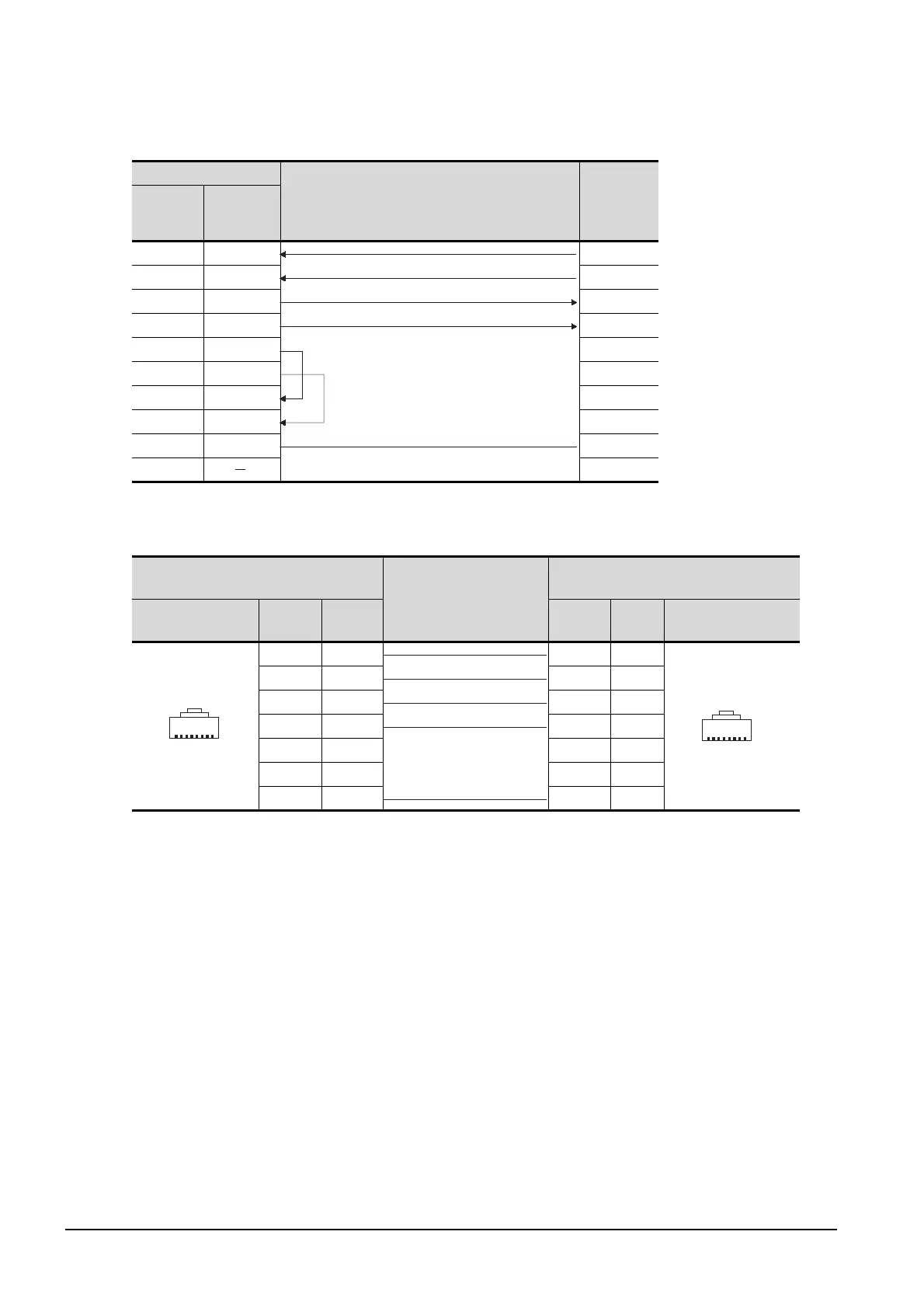
(2) RS-422 cable 2)
(3) RS-422 cable 3)
*1 The connector figure shows the engagement face.
GOT side
Cable connection and signal direction
FR-A5NR
side
(Terminal
block)
Signal
name
Pin No.
RDA 2 SDA
RDB 7 SDB
SDA 1 RDA
SDB 6 RDB
RSA 3
RSB 8
CSA 4
CSB 9
SG 5 SG
FG
Distributor side
(Modular connector)
Cable connection and signal
direction
inverter side or distributor side
(Modular connector)
Pin layout
*1
Signal
name
Pin No. Pin No.
Signal
name
Pin layout
*1
SDA 5 5 SDA
SDB 4 4 SDB
RDA 3 3 RDA
RDB 6 6 RDB
P5S 2 2 P5S
P5S 8 8 P5S
SG 1 1 SG
1
8
PU port
PJ-45 plug(male)
1
8
PU port
PJ-45 plug(male)

Table of Contents

Related product manuals