23.2 Connection Cable
23 - 9
17
CONNECTION TO
ALLEN-BRADLEY PLC
18
CONNECTION TO
SIEMENS PLC
19
MICROCOMPUTER
CONNECTION
20
CONNECTION TO OMRON
TEMPERATURE
CONTROLLER
21
CONNECTION TO
YAMATAKE TEMPERATURE
CONTROLLER
22
CONNECTION TO RKC
TEMPERATURE
CONTROLLER
23
CONNECTION TO
FREQROL SERIES
INVERTER
24
SERVO AMPLIFIER
CONNECTION
23.2 Connection Cable
The RS-422 cable used for connecting the GOT to the inverter should be prepared by the user.
The following provides connection diagrams for each cable, connector specifications and other information.
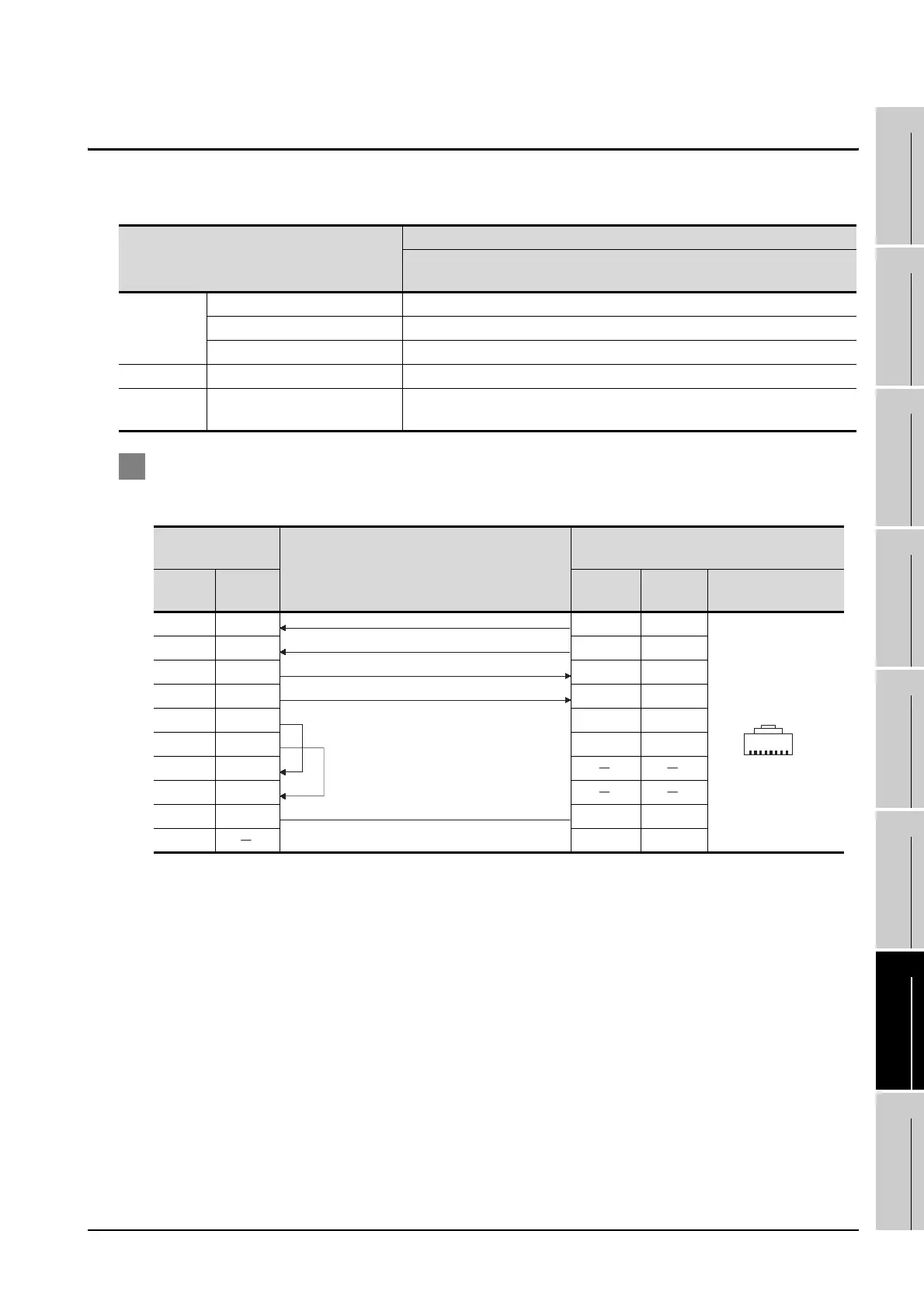
1 Connection diagram
(1) RS-422 cable 1)
*1 The connector figure shows the engagement face.
Model name
Connection cable
RS-422 cable
(Section 23.2)
FREQROL
A500/F500 RS-422 cable 1), RS-422 cable 2), RS-422 cable 4)
E500/ S500 RS-422 cable 1)
A700/F700 RS-422 cable 1), RS-422 cable 5), RS-422 cable 6)
Distributor BMJ-8 RS-422 cable 1), RS-422 cable 3), RS-422 cable 7)
Computer link
option
FR-A5NR RS-422 cable 4), RS-422 cable 5)
GOT side
Cable connection and signal direction
Inverter side
(Modular connector)
Signal
name
Pin No. Pin No.
Signal
name
Pin layout
1
RDA 2 5 SDA
RDB 7 4 SDB
SDA 1 3 RDA
SDB 6 6 RDB
RSA 3 2 P5S
RSB 8 8 P5S
CSA 4
CSB 9
SG 5 1 SG
FG
1
8
PJ-45 plug(male)
PU port

 Loading...


