EasyManuals Logo

Mitsubishi GOT1000 Series User Manual

Mitsubishi GOT1000 Series
1216 pages
To Next Page IconTo Next Page
To Previous Page IconTo Previous Page
Page #956 background imageLoading...
Page #956 background image
23 - 14
23.2 Connection Cable
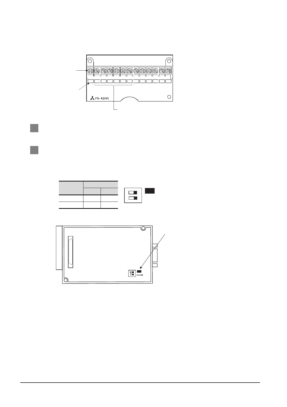
(3) Terminal block layout in the FR-A5NR computer link option
Attach this option to the A500 and F500 Series.
3 Precations when preparing a cable
The length of the RS-422 cable must be 1200m or less.
4 Connecting terminating resistors
(1) GOT
Set the terminating resistor of RS-422/485 communication unit using the terminating resistor
setting switch of RS-422/485 communication unit.
*1 The default setting is “Enable”.
Term inat ing
resistor
*1
Switch No.
1 2
Enable ON ON
Disable OFF OFF
SDBSDA RDA RDB RDR SG A
B
C
Connected to the GOT
Terminal block
Screw size: M3
Terminal symbol
SW1
ON
12
ON
SW1
ON
12
Terminating resistor setting switch
(When using GT15-RS4-9S)
Rear view of RS-422/485 communication unit

Table of Contents

Questions and Answers:

Question and Answer IconNeed help?

Do you have a question about the Mitsubishi GOT1000 Series and is the answer not in the manual?

Mitsubishi GOT1000 Series Specifications

General IconGeneral
Power Supply24 VDC
TypeHMI (Human Machine Interface)
SeriesGOT1000
Resolution640 x 480 pixels
Touch Panel TypeResistive
InterfaceRS-232, USB
Storage Temperature-20 to 60°C
Protection RatingIP65
Display TypeTFT LCD
Brightness400 cd/m²
Backlight Life50, 000 hours
CPURISC
Shock Resistance147 m/s²
Display Size10.4 inches

Related product manuals