EasyManua.ls Logo

Mitsubishi GOT1000 Series - Page 985

Mitsubishi GOT1000 Series
1216 pages
To Next Page IconTo Next Page
To Previous Page IconTo Previous Page
Loading...
24.2 Connection Cable
24.2.2 RS-422 cable
24 - 11
17
CONNECTION TO
ALLEN-BRADLEY PLC
18
CONNECTION TO
SIEMENS PLC
19
MICROCOMPUTER
CONNECTION
20
CONNECTION TO OMRON
TEMPERATURE
CONTROLLER
21
CONNECTION TO
YAMATAKE TEMPERATURE
CONTROLLER
22
CONNECTION TO RKC
TEMPERATURE
CONTROLLER
23
CONNECTION TO
FREQROL SERIES
INVERTER
24
SERVO AMPLIFIER
CONNECTION
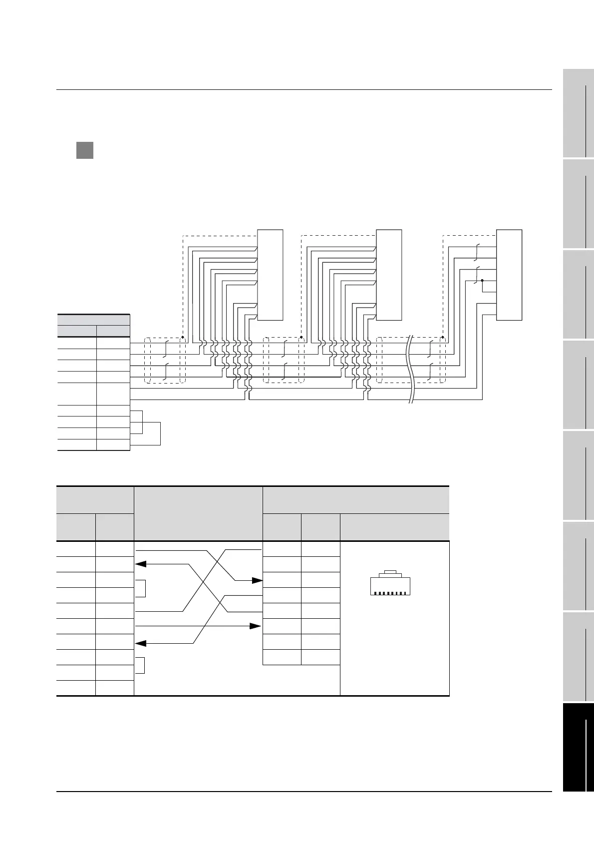
24.2.2 RS-422 cable
The following shows the connection diagrams and connector specifications of the RS-422 cable used for
connecting the GOT to a servo amplifier.
1 Connection diagram
(1) RS-422 cable 1)
(2) RS-422 cable 3)
*1 The pin layout shows the engagement face.
GOT side
cable connection
Distributor side
(Modular connector)
Signal
name
Pin No.
Pin
wiring
Signal
name
Pin layout*1
SDA 1
1 LG
RDA 2
2 P5
RSA 3 3 RDP
CSA 4 4 SDN
SG 5 5 SDP
SDB 6 6 RDN
RDB 7 7 LG
RSB 8 8 TRE
CSB 9
FG -
1
11
9
Plate
5
19
10
15
11
SDP
SD
RDP
SDN
TRE
RDN
LG
LG
9
5
19
10
15
11
SDP
SD
RDP
SDN
TRE
RDN
LG
LG
9
5
19
10
15
11
SDP
SD
RDP
SDN
TRE
RDN
LG
LG
PlatePlate
Connector for
interface unit's
or
1st axis servo
amplifier's CN3
Connector for
interface unit's
or
2nd axis servo
amplifier's CN3
Connector for
interface unit's
or
32nd axis (last axis)
servo amplifier's CN3 (*1)
*1 At the last axis, connect TRE to RDN.
RXD-(RDA)
Signal name Pin No.
GOT side
2
TXD+(SDA) 1
TXD-(SDB) 6
SG(GND) 5
RTS+(RSA) 3
RTS-(RSB) 8
CTS+(CSA) 4
CTS-(CSB) 9
RXD+(RDB) 7
PJ-45 plug(male)
18

Table of Contents

Related product manuals