8 - 8
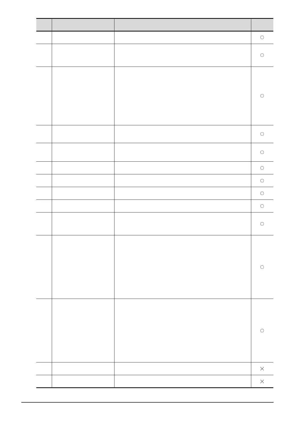
8.2 Error Codes and System Alarm List
404
Response does not match
communication request.
• Resolve crosstalk on the line.
• Lengthen the communication timeout time.
406
Specified station access is out of
range. Confirm station no.
• Station numbers other than master/local station are specified at the CC-Link
connection (via G4).
• A PLC CPU other than QCPU is accessed.
Confirm the station number of the project data.
407
Accessed other network. Change
network setting.
• When monitoring the same network as the GOT
The GOT accesses the other networks with the MELSECNET/H, MELSECNET/10
(PLC to PLC network), or CC-Link IE Controller Network connection. Confirm the
network number of the project data so as not to access to other networks.
• When monitoring other networks
Reconfigure the [Routing Information Setting] of GT Designer3 or the [Routing
Information Setting] of GX Developer.
• When using GT15-75J71LP23-Z/ GT15-75J71BR13-Z
Other networks cannot be monitored.
Confirm the network number of the project data so as not to access to other
networks.
410
Cannot perform operation because
of PLC run mode. stop the PLC.
The operation, which could not be performed during RUN of PLC CPU, was
performed.
Stop the PLC CPU.
411
Memory cassette is write-protected.
Check the memory cassette.
The memory cassette installed in the PLC CPU is EPROM or E
2
PROM, and it is in a
protected status.
Confirm the memory cassette installed in PLC CPU.
412
Cannot read/write device protected
by keyword. Remove keyword.
The key word is set in PLC CPU.
Cancel the key word.
413
Unsupported CPU has been
accessed.
• Check the latest manual to see if the CPU is supported.
• Write package data created with the latest version of GT Designer3.
420 E71 specification is ASCII.
[ASCII code] is selected in [Ethernet operations] of the PLC side setting.
Select [Binary code].
421 E71 is set as read-only. Clear setting.
The Ethernet module on the PLC side is set in read-only.
Set the Ethernet module on the PLC side to write-enabled.
422
Not communicating between CPU
and E71. Confirm CPU error.
PLC CPU error. Communication between PLC CPU and the PLC side Ethernet
module impossible.
Confirm whether there is error in PLC CPU by GX Developer etc. (Confirm buffer
memory)
423
Insufficient network table information.
Add station no.
The station number set in the project data and the station number set in the switching
station No. device do not exist in the Ethernet setting of GT Designer3.
• Add the station number set in the project data to the Ethernet setting of GT
Designer3.
• When using the station No. switching function, check the data of the switching
station No. device.
When the station number specified in the switching station No. device is not set in
the Ethernet setting, add the station number to the Ethernet setting.
When the station number does not exist in the system, change the data of the
switching station No. device.
(Set the station number so that it becomes the same as the station number of the
PLC side Ethernet module set in the parameter setting of GX Developer.)
424
Same sta. on GOT & project data.
Review communication parameter.
The station number set in the GOT's utility is the same as the station number set in
the Ethernet setting of GT Designer3 (the station number of the PLC side Ethernet
module) or in the project data.
Check the following contents so that the multiple station numbers should not be the
same.
• Check the GOT's station number in the GOT's utility.
• Check the station number set in the project data.
• Check the station number set in the Ethernet setting.
(Set the station number so that it becomes the same as the station number of
the PLC side Ethernet module set in the parameter setting of GX Developer.)
• When using the station No. switching function, check the data of the switching
station No. device.
431
Connectable access point is not
found.
Check the setting for an accessible access point, and the wireless LAN connection
setting.
432
Wireless LAN connection settings
are not specified.
After configuring the wireless LAN connection setting, enable the wireless LAN
connection function.
Error
code
Error message Action
Channel
No. storage

 Loading...


