16 - 4
16.1 Device Monitor Function
16.1.5 Information displayed on the device monitor screen and key functions
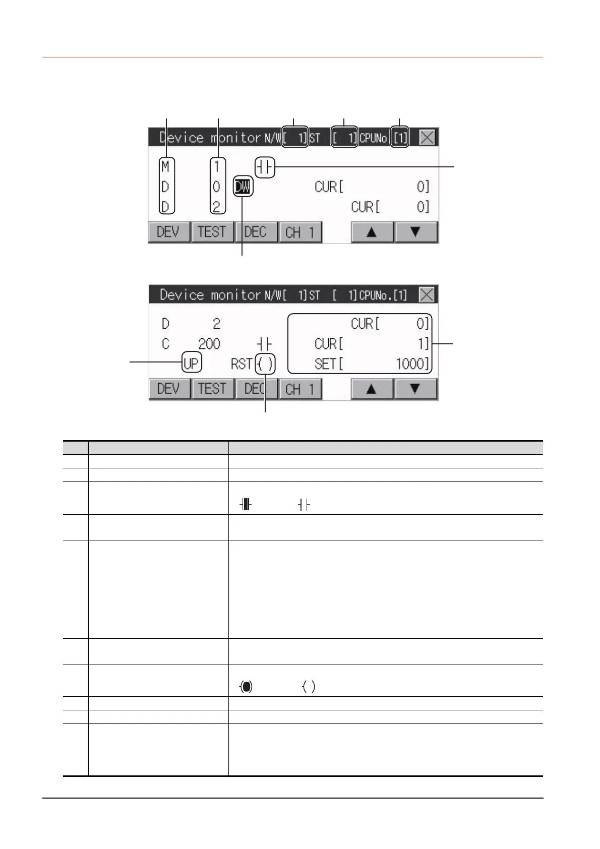
■1. Device monitor screen
The information displayed on the device monitor screen is described below.
*1 When a timer or counter of the ACPU, QnACPU, or FXCPU is registered, the set value of the timer or counter is displayed.
No. Item Settings
1) Device name Displays the device name.
2) Device No. Displays the device number.
3)
Bit device ON/OFF
Timer/Counter contact ON/OFF
Displays ON/OFF information of bit devices and timer/counter contacts
: ON : OFF
4) Data type
DW: Indicates that the device value is a 32-bit (two-word) module.
Nothing displayed: Indicates that the device value is a 16-bit (one-word) module.
5)
Present value of word device
Present value and set value of timer/
counter
*1
[Decimal number]
16-bit (one-word) module: Six digits (including a digit for a sign) are displayed. (Display
example: -12345)
32-bit (two-word) module: Ten digits (including a digit for a sign) are displayed.
(Display example: -123456789)
[Hexadecimal number]
16-bit (one-word) module: Four digits are displayed. (Display example: H AB12)
32-bit (two-word) module: Eight digits are displayed. (Display example: H ABCDE123)
6) Counting method
Displays the counting method when registering the counters from C200 to C255.
UP: Up count mode DOWN: Down count mode
7) Reset coil ON/OFF
Displays the reset coil state when registering the timer/counter for the FXCPU.
: ON : OFF
8) Network No. Sets or displays the network No. when the PLC is on the network.
9) Station No. Sets or displays the station No. when the station No. is assigned to the PLC.
10) CPU No. specification
0 to 4: This item must be set only when the GOT is connected to the Q series CPU in
the multiple CPU system or QnUCPU.
Changing the CPU No. cancels the registration for all the devices.
➠ 16.1.7 Device registration
1) 2) 8) 9) 10)
4)
3)
5)
6)
7)

 Loading...


