114
5 SEQUENCE INSTRUCTIONS
5.3 Output Instructions
Setting devices (excluding annunciator)
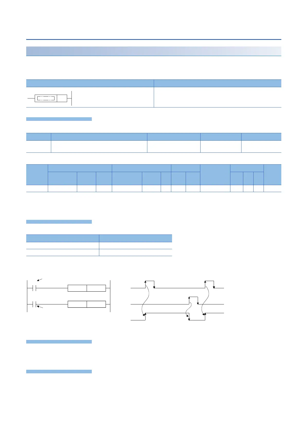
SET
The status of the device specified by (d) changes as follows when the execution command turns ON.
• Bit device: Turns the coils and contacts ON.
• Bit specification of word device: Set the specified bit to 1.
■Descriptions, ranges, and data types
■Applicable devices
*1 When using F, refer to Page 116.
*2 Only the FX5 series intelligent function module can be used.
*3 T, ST, C cannot be used.
• The status of the specified device changes as follows when the execution command turns ON.
• A device that is turned ON is held on even if the execution command turns OFF. Devices that are turned ON by the SET
instruction can be turned OFF by the RST instruction.
• When the execution command is OFF, the device status does not change.
When the SET and RST instructions are executed on the same output relay (Y), the result of the instruction nearer the END
instruction (end of program) is output.
There is no operation error.
Ladder diagram Structured text
ENO:=SET(EN,d);
Operand Remarks Range Data type Data type (label)
(d) Bit device number/ Bit specification of word device to be
set (turns ON)
Bit ANY_BOOL
Operand Bit Word Double word Indirect
specification
Constant Others
(DY)
X, Y, M, L,
SM, F, B, SB
U\G T, ST,
C, LC
T, ST, C, D,
W, SD, SW, R
U\G Z LC LZ K, H E $
(d)
*1
*2
*3
Device Device status
Bit devices Turns coils and contacts ON.
Bit specification of word device Sets the specified bit to 1.
SET Y10
RST Y10
X5
X7
X5 OFF
X7 OFF
Y10 OFF
ON
ON
ON
Command
Command
 Loading...

