258
6 BASIC INSTRUCTIONS
6.5 Data Conversion Instructions
Converting 16-bit unsigned binary data to 32-bit signed binary
data
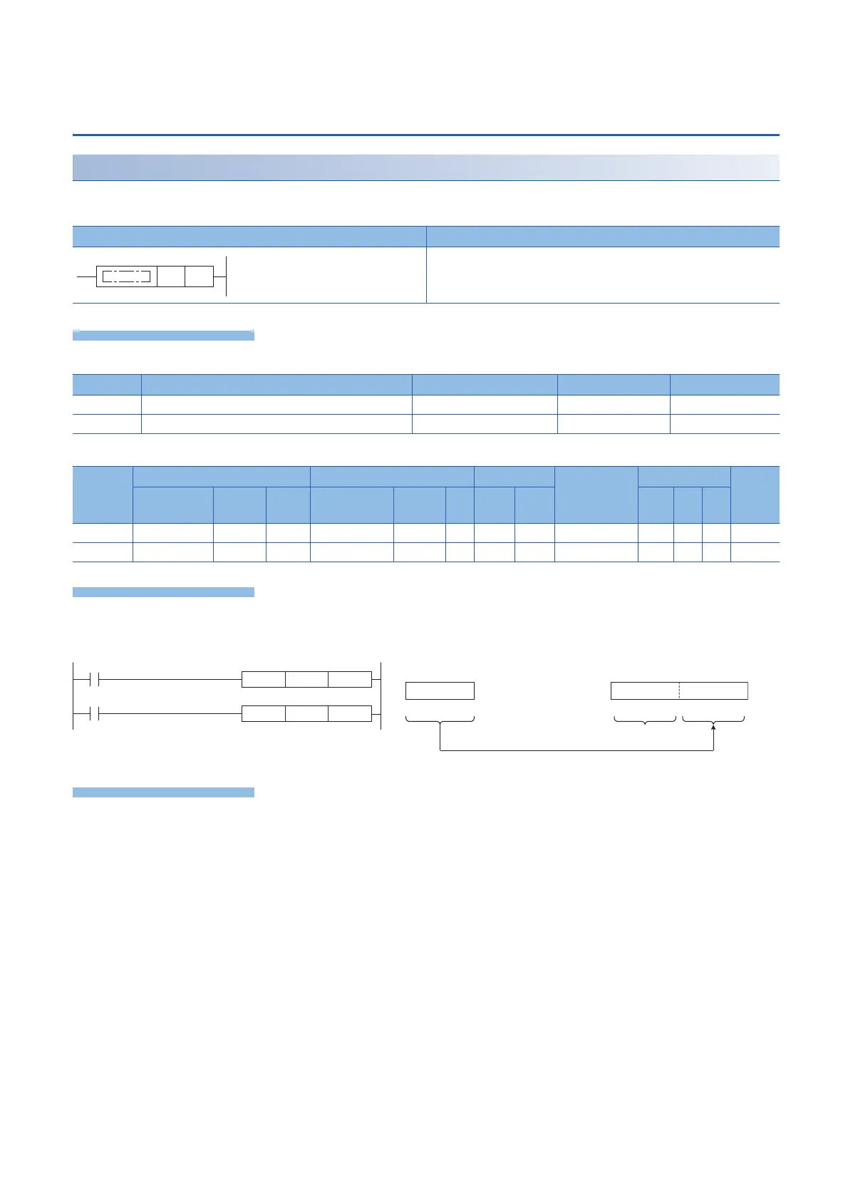
UINT2DINT(P)
These instructions convert the 16-bit unsigned binary data in the device specified by (s) to 32-bit signed binary data, and store
the converted data in the device specified by (d).
■Descriptions, ranges, and data types
■Applicable devices
• These instructions convert the 16-bit unsigned binary data in the device specified by (s) to 32-bit signed binary data, and
store the converted data in the device specified by (d).
There is no operation error.
Ladder diagram Structured text
Not supported
Operand Description Range Data type Data type (label)
(s) Data before conversion 16-bit unsigned binary ANY16_U
(d) Data after conversion 32-bit signed binary ANY32_S
Operand Bit Word Double word Indirect
specification
Constant Others
X, Y, M, L,
SM, F, B, SB
U\G T, ST,
C, LC
T, ST, C, D,
W, SD, SW, R
U\G Z LC LZ K, H E $
(s)
(d)
SM402
M0
(53248)
b31 b16
(53248)
D000H D000H0000HD0
(s)
D101, D100
(d)
b15 b0b15 b0
∙∙∙ ∙∙∙ ∙∙∙
(s) (d)
MOVP H0D000 D0
UINT2DINT
D0 D100
"0" is stored.
Before conversion After conversion
Stores in lower 16 bits
 Loading...

