480
7 APPLICATION INSTRUCTION
7.10 Data control instruction
Zone control of 16-bit binary data
ZONE(P)(_U)
These instructions add the bias value specified by (s1) or (s2) to the input value specified by (s3), and store the operation
result in the device specified by (d).
■Descriptions, ranges, and data types
■Applicable devices
• These instructions add the bias value specified by (s1) or (s2) to the input value (16-bit binary data) specified by (s3), and
store the operation result in the device specified by (d). The bias value is controlled as follows.
• When the output value to be stored in the device specified by (d) is a 16-bit signed binary value and the operation result
exceeds the range of -32768 to 32767, the output value is calculated as follows.
Ladder diagram Structured text
ENO:=ZONE(EN,s1,s2,s3,d);
ENO:=ZONEP(EN,s1,s2,s3,d);
ENO:=ZONE_U(EN,s1,s2,s3,d);
ENO:=ZONEP_U(EN,s1,s2,s3,d);
Operand Description Range Data type Data type (label)
(s1) ZONE(P) Negative bias value to be added to the input value -32768 to +32767 16-bit signed binary ANY16
ZONE(P)_U 0 to 65535 16-bit unsigned binary
(s2) ZONE(P) Positive bias value to be added to the input value -32768 to +32767 16-bit signed binary ANY16
ZONE(P)_U 0 to 65535 16-bit unsigned binary
(s3) ZONE(P) Input value for performing the zone control -32768 to +32767 16-bit signed binary ANY16
ZONE(P)_U 0 to 65535 16-bit unsigned binary
(d) ZONE(P) Head device number storing the output value controlled by
the zone
16-bit signed binary ANY16
ZONE(P)_U 16-bit unsigned binary
Operand Bit Word Double word Indirect
specification
Constant Others
X, Y, M, L,
SM, F, B, SB
U\G T, ST,
C, LC
T, ST, C, D,
W, SD, SW, R
U\G Z LC LZ K, H E $
(s1)
(s2)
(s3)
(d)
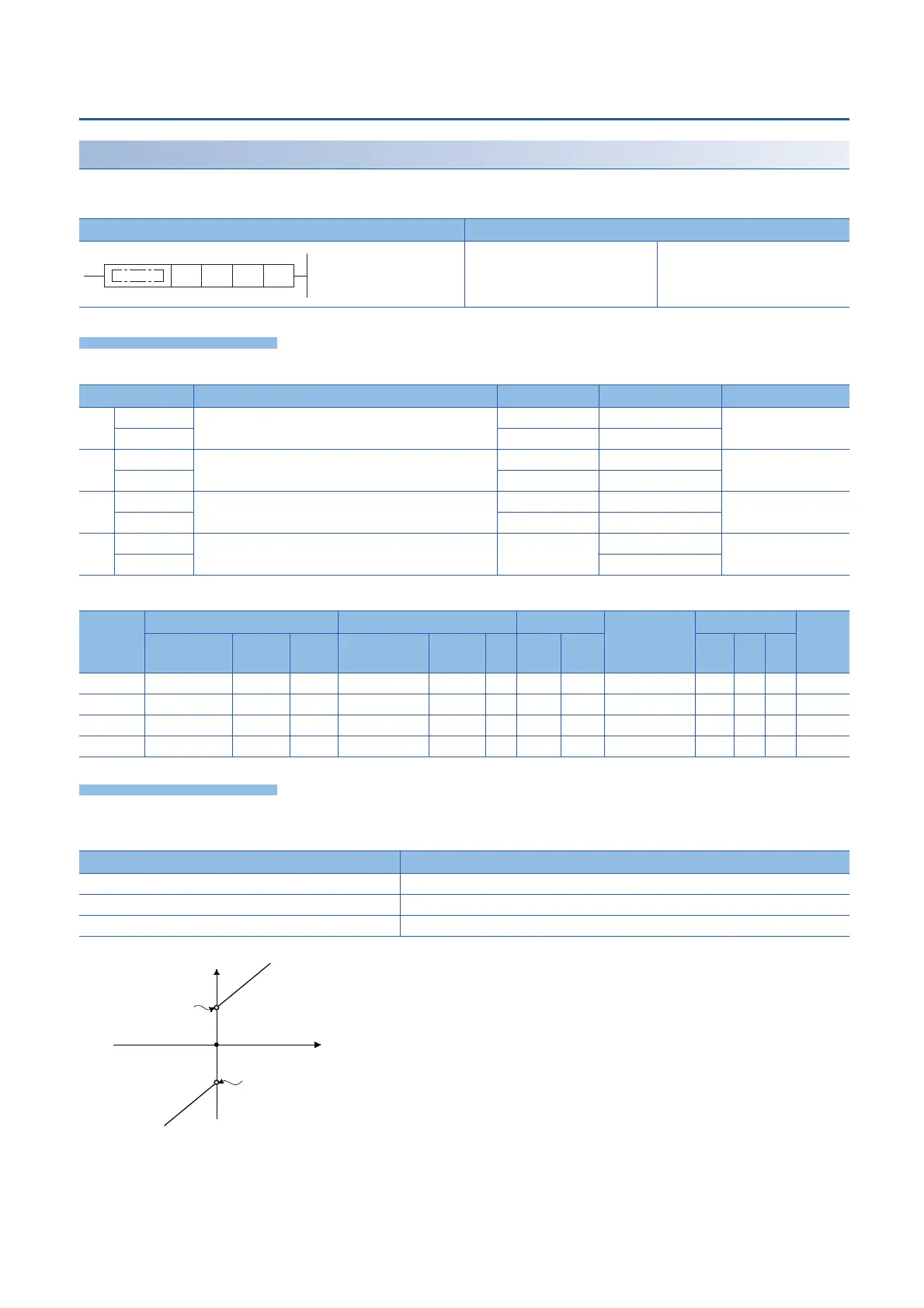
Condition Output value
Input value (s3) < 0 Input value (s3) + Negative bias value (s1)
Input value (s3) = 0 0
Input value (s3) > 0 Input value (s3) + Positive bias value (s2)
0
Output value (d)
Input value (s3)
Negative bias value (s1)
Positive bias value (s2)
 Loading...

