660
11 POSITIONING INSTRUCTION
11.1 Positioning Instruction
Multiple axes concurrent drive positioning
DRVMUL
This instruction executes tables of multiple axes of one module simultaneously.
■Descriptions, ranges, and data types
■Applicable devices
*1 T, ST, C cannot be used.
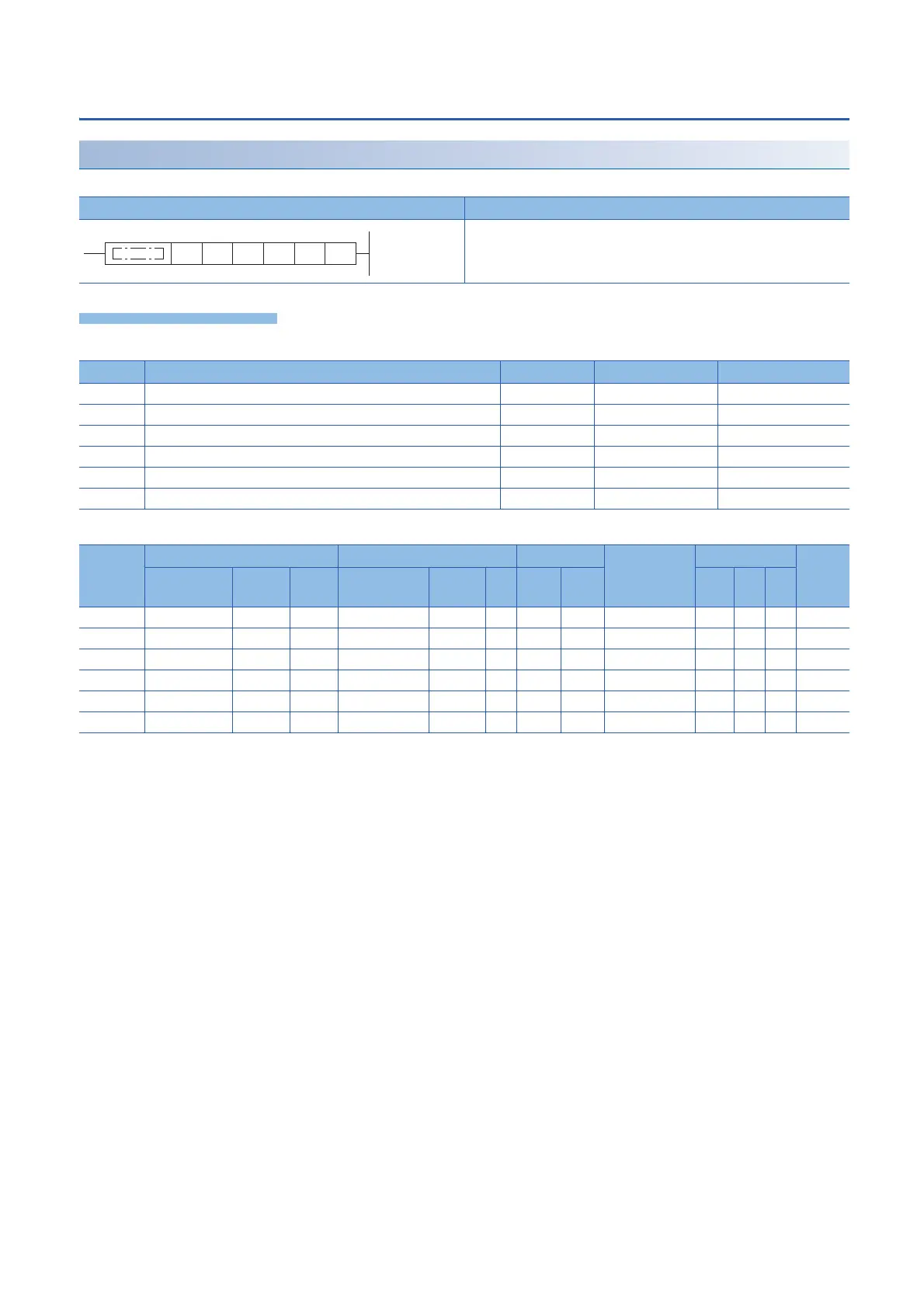
Ladder diagram Structured text
ENO:=DRVMUL(EN,n1,n2,n3,n4,n5,d);
Operand Description Range Data type Data type (label)
(n1) Start axis number K1 16-bit unsigned binary ANY16_U
(n2) Table number of the axis 1 K0 to 100 16-bit unsigned binary ANY16_U
(n3) Table number of the axis 2 K0 to 100 16-bit unsigned binary ANY16_U
(n4) Table number of the axis 3 K0 to 100 16-bit unsigned binary ANY16_U
(n5) Table number of the axis 4 K0 to 100 16-bit unsigned binary ANY16_U
(d) Bit device number of the positioning complete flag or abnormal end flag Bit ANY_BOOL
Operand Bit Word Double word Indirect
specification
Constant Others
X, Y, M, L,
SM, F, B, SB
U\G T, ST,
C, LC
T, ST, C, D,
W, SD, SW, R
U\G Z LC LZ K, H E $
(n1)
(n2)
(n3)
(n4)
(n5)
(d)
*1
(n2) (n3) (n4) (n5) (d)(n1)
 Loading...

