7 APPLICATION INSTRUCTION
7.14 Pulse related instruction
521
7
32 bit binary pulse output
DPLSY [For the FX3 Series-compatible operand specification]
This instruction outputs 32-bit pulse trains specified by the command speed (s) from the device specified by the output (d) for
the amount of 32-bit pulses specified by the positioning address (n).
■Descriptions, ranges, and data types
■Applicable devices
*1 Y0 to Y3 can be used.
• This instruction outputs 32-bit pulse trains specified by the command speed (s) from the device specified by the output (d)
for the amount of 32-bit pulses specified by the positioning address (n).
• Set the value from 0 to 2147483647 (in user unit) to the command speed (s), so that the command speed is 200 kpps or
less when the command speed is converted to frequency.
• Set the value from 0 to 2147483647 (in user unit) to the positioning address (n), so that the positioning address is within the
range from 0 to 2147483647 when the positioning address is converted to number of pulses.
• Specify the Y device number (Y0 to Y3) in (d).
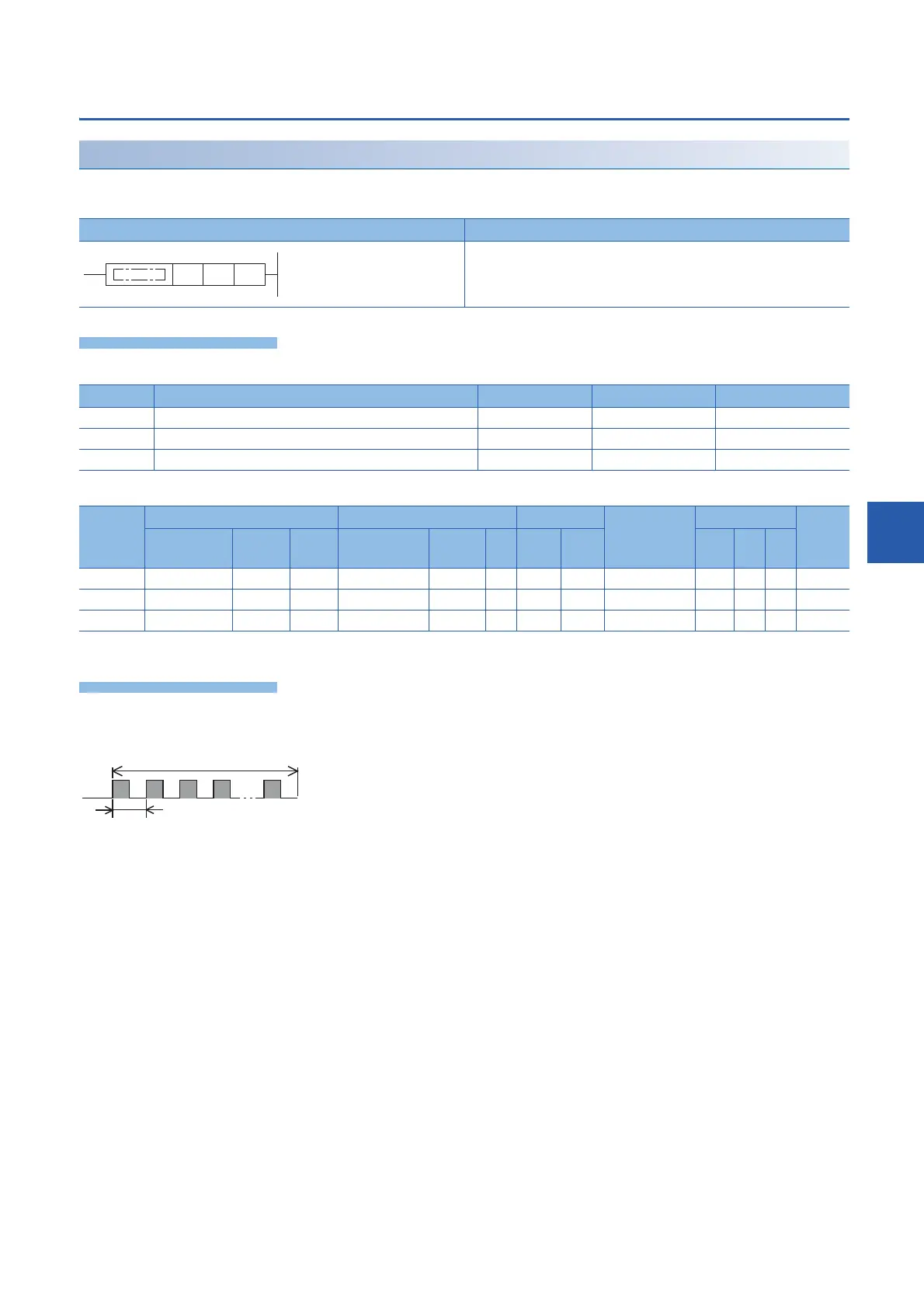
Ladder diagram Structured text
ENO:=DPLSY(EN,s,n,d);
Operand Description Range Data type Data type (label)
(s) Command speed or word device number storing data 0 to 2147483647 32-bit unsigned binary ANY32
(n) Positioning address or word device number storing data 0 to 2147483647 32-bit unsigned binary ANY32
(d) Bit device number from which pulses are to be output 0 to 3 Bit ANY_BOOL
Operand Bit Word Double word Indirect
specification
Constant Others
X, Y, M, L,
SM, F, B, SB
U\G T, ST,
C, LC
T, ST, C, D,
W, SD, SW, R
U\G Z LC LZ K, H E $
(s)
(n)
(d)
*1
[(s)+1, (s) Command speed]
[(n)+1, (n) Positioning address]
 Loading...

