640
9 HIGH-SPEED COUNTER INSTRUCTION
9.1 High-speed Processing Instruction
Start/stop of the 16-bit data high-speed I/O function
HIOEN(P)
These instructions control the start and stop operations of a high-speed I/O function.
■Descriptions, ranges, and data types
■Applicable devices
Specify the number of the function to be started or stopped in (s1), the bit of the channel to be started in (s2), and the bit of the
channel to be stopped in (s3).
The following table shows the function numbers which can be specified in (s1).
*1 When high-speed counter (function number: 0) is stopped during function operation, the function continues to operate, but nothing will
be processed.
*2 When multi-output high-speed comparison table (function number: 30) is stopped, high-speed counter of the same ch is also stopped.
The following table shows the values which can be specified in (s2) and (s3) for each function number.
Function number 0
The counting start and stop of a high-speed counter can be controlled for each channel of high-speed counter.
To start CH3, set 04H in (s2). To stop it, set 04H in (s3).
To start CH1, CH4, and CH5, set 19H in (s2). To stop them, set 19H in (s3).
To start CH1 and CH4 and to stop CH5, set 09H in (s2) and set 10H in (s3).
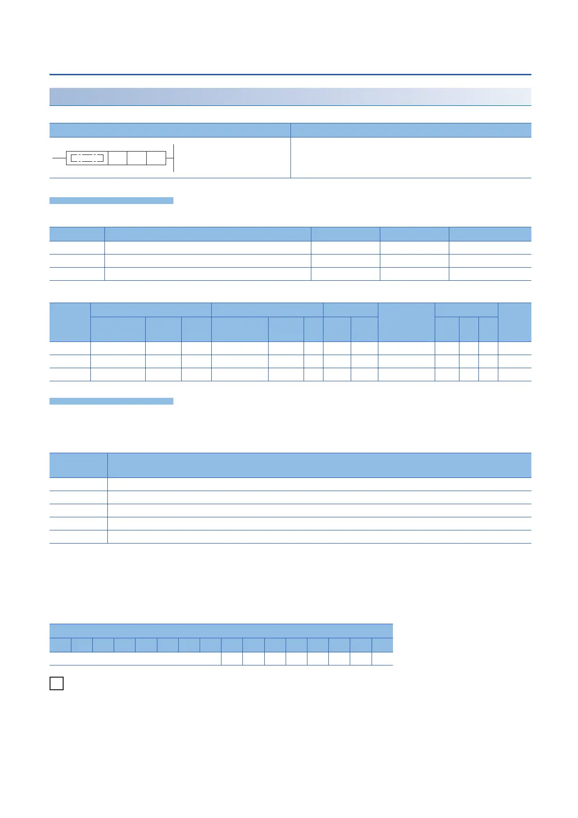
Ladder diagram Structured text
ENO:=HIOEN(EN,s1,s2,s3);
ENO:=HIOENP(EN,s1,s2,s3);
Operand Description Range Data type Data type (label)
(s1) Function number to be started or stopped K0 to 50 16-bit signed binary ANY16
(s2) Set the bit of the channel number where the function is started. -32768 to +32767 16-bit signed binary ANY16
(s3) Set the bit of the channel number where the function is stopped. -32768 to +32767 16-bit signed binary ANY16
Operand Bit Word Double word Indirect
specification
Constant Others
X, Y, M, L,
SM, F, B, SB
U\G T, ST,
C, LC
T, ST, C, D,
W, SD, SW, R
U\G Z LC LZ K, H E $
(s1)
(s2)
(s3)
Function
number
Function name
0 High-speed counter
10
*1
Pulse density/rotation speed measurement
30
*1*2
Multi-output high-speed comparison table
40 Pulse width measurement
50 PWM
Bit position
b15 b14 b13 b12 b11 b10 b9 b8 b7 b6 b5 b4 b3 b2 b1 b0
CH8 CH7 CH6 CH5 CH4 CH3 CH2 CH1
 Loading...

