11 POSITIONING INSTRUCTION
11.1 Positioning Instruction
663
11
16-bit data variable speed pulse
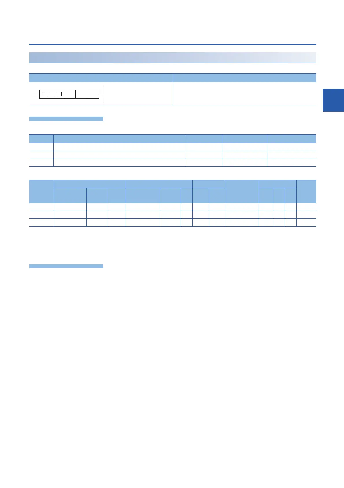
PLSV [For the FX3 Series-compatible operand specification]
This instruction outputs variable speed pulses with an assigned rotation direction output.
■Descriptions, ranges, and data types
■Applicable devices
*1 Only Y can be used.
*2 When the output mode is CW/CCW, specify the CCW axis. When the output mode is PULSE/SIGN and using Y, only the SIGN output or
general-purpose output of the self-axis can be specified.
*3 T, ST, C cannot be used.
This instruction outputs variable speed pulses with an assigned rotation direction output.
• For (s), specify the command speed to be output. (The speed must be 200 Kpps or lower in frequency.)
• For (d1), specify the device from which pulses are output. Only the output devices (Y) having positioning parameters can
be specified.
• For (d2), specify the device from which the rotation direction signal is output. Only the device specified with the parameter
or general-purpose outputs can be specified. When the output devices (Y) is executed by another function (PWM,
positioning PULSE axis, or CW/CCW axis etc.), the device does not function and causes an error.
For details on the function, precautions, and error code, refer to Built-in positioning manual.
Ladder diagram Structured text
ENO:=PLSV(EN,s,d1,d2);
Operand Description Range Data type Data type (label)
(s) Command speed -32768 to +32767 16-bit signed binary ANY16
(d1) Bit device number (Y) from which pulses are output 0 to 3 Bit ANY_ELEMENTARY
(d2) Bit device number from which the rotation direction is output Bit ANY_BOOL
Operand Bit Word Double word Indirect
specification
Constant Others
X, Y, M, L,
SM, F, B, SB
U\G T, ST,
C, LC
T, ST, C, D,
W, SD, SW, R
U\G Z LC LZ K, H E $
(s)
(d1)
*1
(d2)
*2
*3

 Loading...


