EasyManua.ls Logo

Mitsubishi MELSEC iQ-F FX5 series User Manual

Mitsubishi MELSEC iQ-F FX5 series
888 pages
To Next Page IconTo Next Page
To Previous Page IconTo Previous Page
Page #451 background imageLoading...
Page #451 background image
7 APPLICATION INSTRUCTION
7.7 Real Number Instruction
449
7
Calculating the arc tangent of single-precision real number
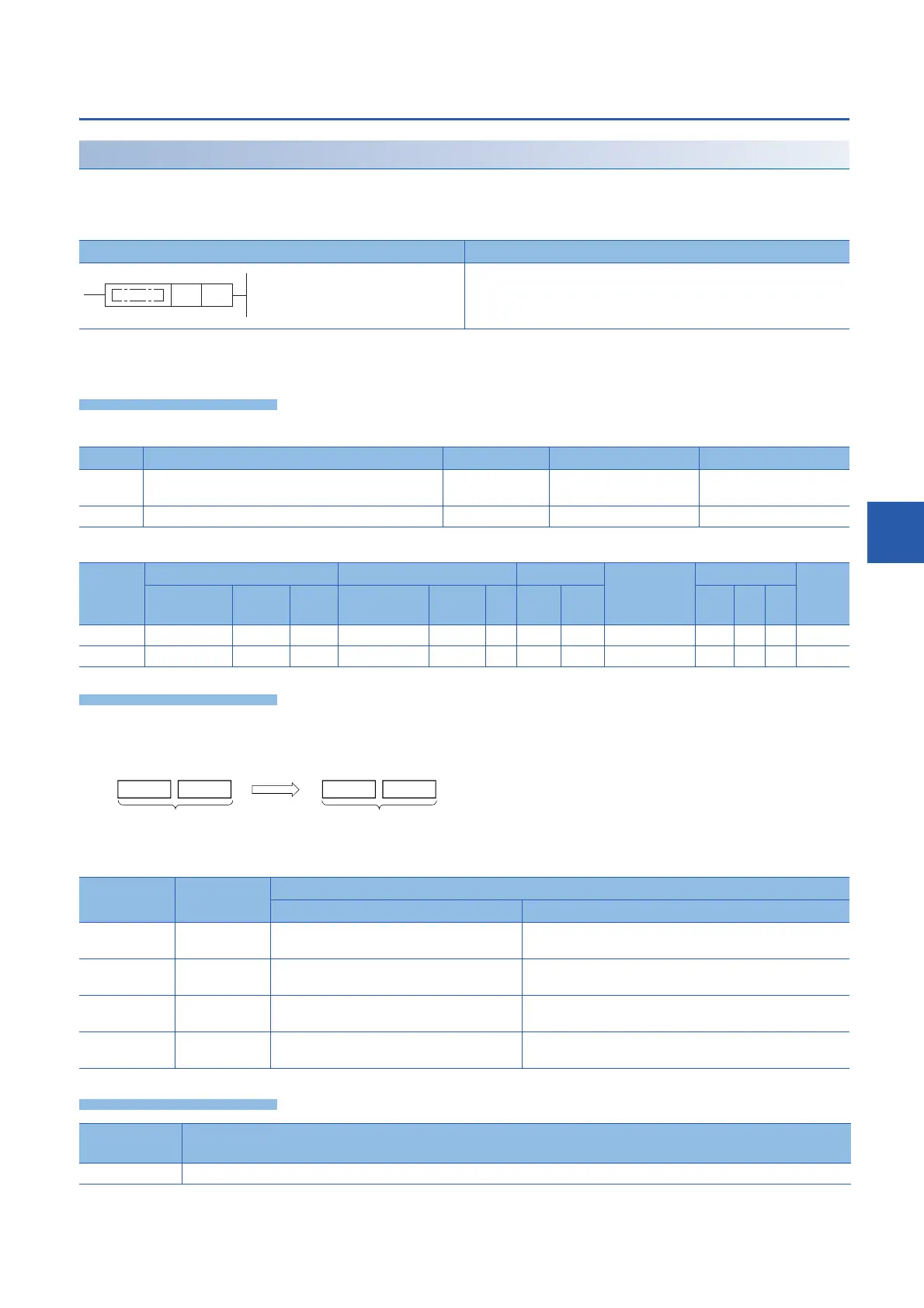
ATAN(P)/DATAN(P)
These instructions calculate the angle from the tangent of the angle specified by (s), and store the operation result in the word
device specified by (d).
The ATAN(P) instructions can also be used as DATAN(P).
*1 The ATAN instruction is not supported by the ST language. Use ATAN of the standard function.
Page 776 ATAN(_E)
Setting data
Descriptions, ranges, and data types
Applicable devices
Processing details
These instructions calculate the angle from the tangent of the angle specified by (s), and store the operation result in the
device specified by (d).
The angle (operation result) stored in (d) is expressed in radians (from -/2 to /2).
The table below shows the related devices.
Operation error
Ladder diagram Structured text
*1
ENO:=ATANP(EN,s,d);
Operand Description Range Data type Data type (label)
(s) A tangent value used in the TAN
-1
(arc tangent) operation or
head device number storing the tangent value
Single-precision real number Single-precision real number
(d) Head device number for storing the operation result -/2 to +/2 Single-precision real number Single-precision real number
Operand Bit Word Double word Indirect
specification
Constant Others
X, Y, M, L,
SM, F, B, SB
U\G T, ST,
C, LC
T, ST, C, D,
W, SD, SW, R
U\G Z LC LZ K, H E $
(s) 
(d)  
Device Name Description
Condition Operation
SM700 Carry The absolute value of the operation result 2
128
The value of (d) is the maximum value (2
128
) of 32-bit real
numbers and the carry flag SM700 turns on.
SM8020 Zero The operation result is true "0".
(The mantissa part is "0").
The zero flag SM8020 turns on.
SM8021 Borrow The absolute value of the operation result < 2
-126
The value of (d) is the minimum value (2
-126
) of 32-bit real
numbers and the borrow flag SM8021 turns on.
SM8022 Carry The absolute value of the operation result
2
128
The value of (d) is the maximum value (2
128
) of 32-bit real
numbers and the carry flag SM8022 turns on.
Error code
(SD0/SD8067)
Description
3402 The specified device value is -0, denormalized number, NaN (not a number), or .
(s) (d)
(s)+1 (s) (d)+1 (d)
TAN
-1
( )
Single-precision real number Single-precision real number

Table of Contents

Question and Answer IconNeed help?

Do you have a question about the Mitsubishi MELSEC iQ-F FX5 series and is the answer not in the manual?

Mitsubishi MELSEC iQ-F FX5 series Specifications

General IconGeneral
SeriesMELSEC iQ-F
Communication InterfacesEthernet, RS-485, USB
TypeProgrammable Logic Controller (PLC)
I/O PointsUp to 256 points (depends on configuration)
Built-in I/OVaries depending on CPU type (e.g., 16, 32, 64)
Programming LanguageLadder Logic, Structured Text, Function Block Diagram, Instruction List, Sequential Function Chart
Communication ProtocolsEthernet, Modbus RTU/ASCII, Modbus TCP, CC-Link IE Field Basic
Expansion ModulesDigital I/O, Analog I/O, Communication
Power Supply24 V DC or 100-240 V AC (depending on model)
Ethernet Port1 port (10/100BASE-TX)
RS-485 Port1 port (depends on model)
USB Port1 port (USB 2.0)
High-speed CounterUp to 200 kHz (depends on model)
Pulse OutputUp to 200 kHz (depends on model)
Operating Temperature0°C to 55°C
Storage Temperature-25°C to 75°C

Summary

SAFETY PRECAUTIONS

INTRODUCTION

Regarding use of this product

Details on the general purpose and specific application considerations for the product.

Note

Important notes regarding installation, operation, manual usage, and potential changes to the manual's content.

PART 1 OVERVIEW

CHAPTER 1 OVERVIEW

Provides a general overview of the CPU module, including instruction configuration, data specification, and execution conditions.

1.1 Instruction Configuration

Explains the structure of instructions, defining instruction and device parts, and detailing source, destination, and numerical data.

1.2 Data Specification Method

Details the various data types usable in CPU modules, including bit, word, double word, and real number data.

1.3 Execution Condition

Describes the five types of execution conditions for instructions: On, Rising edge, Off, Falling edge, and Always.

1.4 Precautions on Programming

Covers common errors, range checks for devices and labels, and operations arising from simultaneous use of instructions.

PART 2 INSTRUCTION/FUNCTION LIST

CHAPTER 2 CPU MODULE INSTRUCTION

Details instructions related to the CPU module, categorized into Sequence, Basic, Module Specific, and Built-in Ethernet.

CHAPTER 3 MODULE SPECIFIC INSTRUCTION

Covers instructions specific to various hardware modules like High-speed Counter, External Device I/O, and Inverter Communication.

CHAPTER 4 STANDARD FUNCTIONS/FUNCTION BLOCKS

Explains standard functions and function blocks, including type conversion, arithmetic operations, and bit shift functions.

PART 3 CPU MODULE INSTRUCTIONS

5 SEQUENCE INSTRUCTIONS

Details sequence instructions including contact, association, output, shift, and master control instructions.

6 BASIC INSTRUCTIONS

Covers fundamental instructions such as comparison, arithmetic, logical, bit processing, data conversion, and data transfer.

7 APPLICATION INSTRUCTION

Explains application-specific instructions like rotation, program branch, execution control, structuring, data table, character string, and real number instructions.

PART 4 MODULE DEDICATED INSTRUCTION

9 HIGH-SPEED COUNTER INSTRUCTION

Details instructions for high-speed processing, including 32-bit data comparison and current value transfer.

10 EXTERNAL DEVICE I/O INSTRUCTION

Covers instructions related to external device communication, specifically Serial Communication 2.

11 POSITIONING INSTRUCTION

Explains instructions for positioning control, including zero return, interrupt positioning, and table operations.

12 INVERTER COMMUNICATION INSTRUCTION

Details instructions for inverter communication, including operation monitoring, parameter read/write, and multi-command.

13 MODBUS COMMUNICATION INSTRUCTION

Covers instructions for MODBUS communication, specifically MODBUS Read/Write.

14 DIVIDED DATA READ/WRITE FROM/TO BFM INSTRUCTION

Explains instructions for divided data read and write operations with BFM.

PART 5 STANDARD FUNCTIONS

CHAPTER 15 TYPE CONVERSION FUNCTIONS

Details various type conversion functions, including BOOL to WORD/DWORD, INT/DINT, TIME, STRING, BCD, REAL, and BIT Array.

CHAPTER 16 SINGLE NUMBER VARIABLE FUNCTIONS

Explains functions operating on single numeric variables like Absolute Value, Square Root, Logarithms, and Trigonometric functions.

CHAPTER 17 ARITHMETIC OPERATION FUNCTIONS

Covers arithmetic functions such as Addition, Multiplication, Subtraction, Division, Remainder, Exponentiation, and Move Operation.

CHAPTER 18 BIT SHIFT FUNCTIONS

Details functions related to bit shifting and rotation, including n-bit shifts and rotations for WORD/DWORD data.

CHAPTER 19 STANDARD BITWISE BOOLEAN FUNCTIONS

Explains standard bitwise operations like AND, OR, XOR, and Logical Negation.

CHAPTER 20 SELECTION FUNCTIONS

Covers selection functions such as Selection (MUX), Maximum/Minimum Value selection, and Limit Control.

CHAPTER 21 COMPARISON FUNCTIONS

Details comparison functions like Compare (GT, GE, EQ, LE, LT, NE) for various data types.

CHAPTER 22 CHARACTER STRING FUNCTIONS

Explains functions for character string manipulation, including length detection, extraction, insertion, deletion, replacement, and searching.

CHAPTER 23 TIME DATA FUNCTIONS

Covers functions related to time data manipulation, including Addition, Subtraction, Multiplication, and Division.

Related product manuals