344
7 APPLICATION INSTRUCTION
7.4 Structuring instruction
Calling a subroutine program
CALL(P)
This instruction executes the subroutine program specified by (P).
■Descriptions, ranges, and data types
■Applicable devices
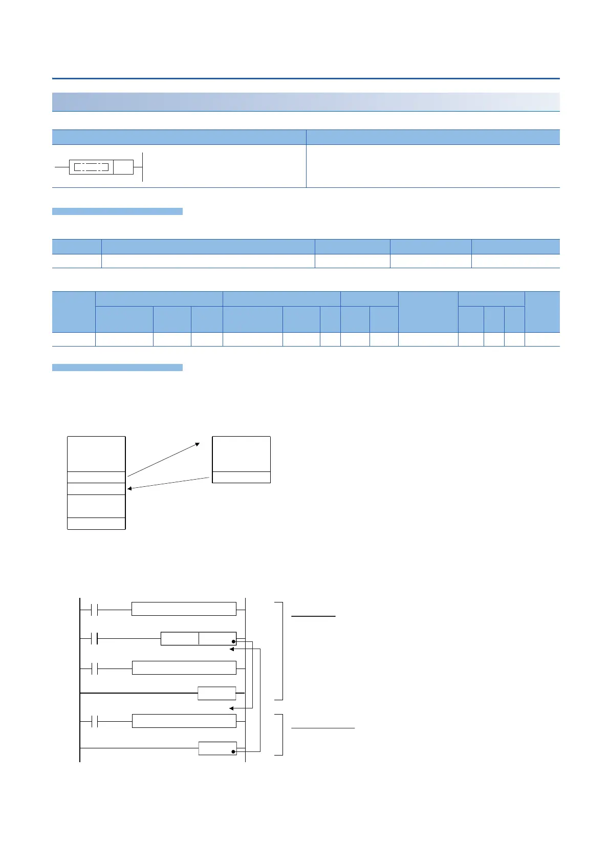
• When the CALL(P) instructions are executed, the subroutine program specified by the pointer (P) is executed. The
CALL(P) instructions can execute a subroutine program specified by a pointer in the same program file or by a common
pointer.
• While the command input is ON, the CALL instruction is executed and the program execution jumps to a step with a label
(Pn). Then, a subroutine program with the label (Pn) is executed. When the RET (SRET) instruction is executed, the
program execution returns to the step following the CALL instruction. At the end of the main program, put FEND instruction.
Put a label (Pn) for the CALL instruction after the FEND instruction.
Ladder diagram Structured text
Not supported
Operand Description Range Data type Data type (label)
(P) Start pointer number of the subroutine program Device name ANY16
Operand Bit Word Double word Indirect
specification
Constant Others
X, Y, M, L,
SM, F, B, SB
U\G T, ST,
C, LC
T, ST, C, D,
W, SD, SW, R
U\G Z LC LZ K, H E $
(P)
CALL (P)
END
(P)
RET(SRET)
Subroutine programMain routine program
PnCALL
FEND
RET
SM400
Command
User program
User program
User program
Main program
Subroutine program
Program area from the step 0 to FEND instruction
Program area from a label Pn to RET instruction
Label
Pn
RUN Monitor
(normally on)
 Loading...

