7 APPLICATION INSTRUCTION
7.4 Structuring instruction
345
7
• The CALL(P) instructions can be nested up to 16 levels. However, the 16 levels are the total of the CALL(P) and XCALL
instructions.
• In the CALL instruction, the same number can be used two or more times in operands (P). However, do not use a label (P)
and number used in another instruction (CJ instruction).
• In a subroutine (or interrupt routine), use timers for routine programs. These timers count when a coil instruction or END
instruction is executed. After a timer reaches the set value, the output contact is activated when the coil instruction or END
instruction is executed. Because general timers count only when the coil instruction is executed, they do not count if they
are used in subroutines in which the coil instruction is executed only under some conditions.
• If a retentive type 1 ms timer is used in a subroutine (interrupt routine), note that the output contact is activated when the
first coil instruction (or subroutine) is executed after the timer reaches its set value.
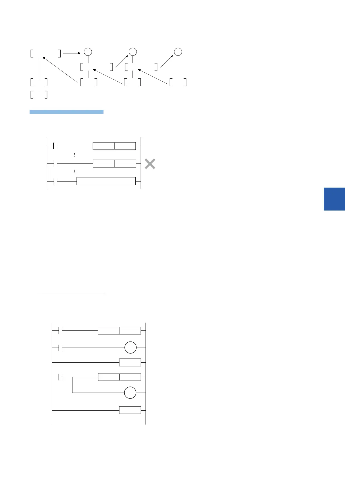
• Devices which were set to ON in a subroutine (or interrupt routine) are latched in the ON status even after the subroutine is
finished. (Refer to the program example shown below). When the RST instruction for a timer or counter is executed, the
reset status of the timer or counter is latched also. For turning OFF such a device latched in the ON status or for canceling
such a timer or counter latched in the reset status, reset such a device in the main program after the subroutine is finished,
or program a sequence for resetting such a device or for deactivating the RST instruction in the subroutine. (Refer to the
program example shown below).
Example in which outputs are latched
In the following program example, the counter C0 is provided to count X1. When X0 is input, the subroutine P0 is executed only in one scan, and then the
counter is reset and Y7 is output.
P0CALL
FEND RET RET RET
END
P0 P10 P20
CALL P10 CALL P20
P9CJ
P9CALLP
X20
X30
User program
Label
P9
X0
P0
P0CALLP
Y7
RET
X1
C0
K10
FEND
X0
C0RST
[Program example]
 Loading...

