7 APPLICATION INSTRUCTION
7.20 Timing check instruction
601
7
7.20 Timing check instruction
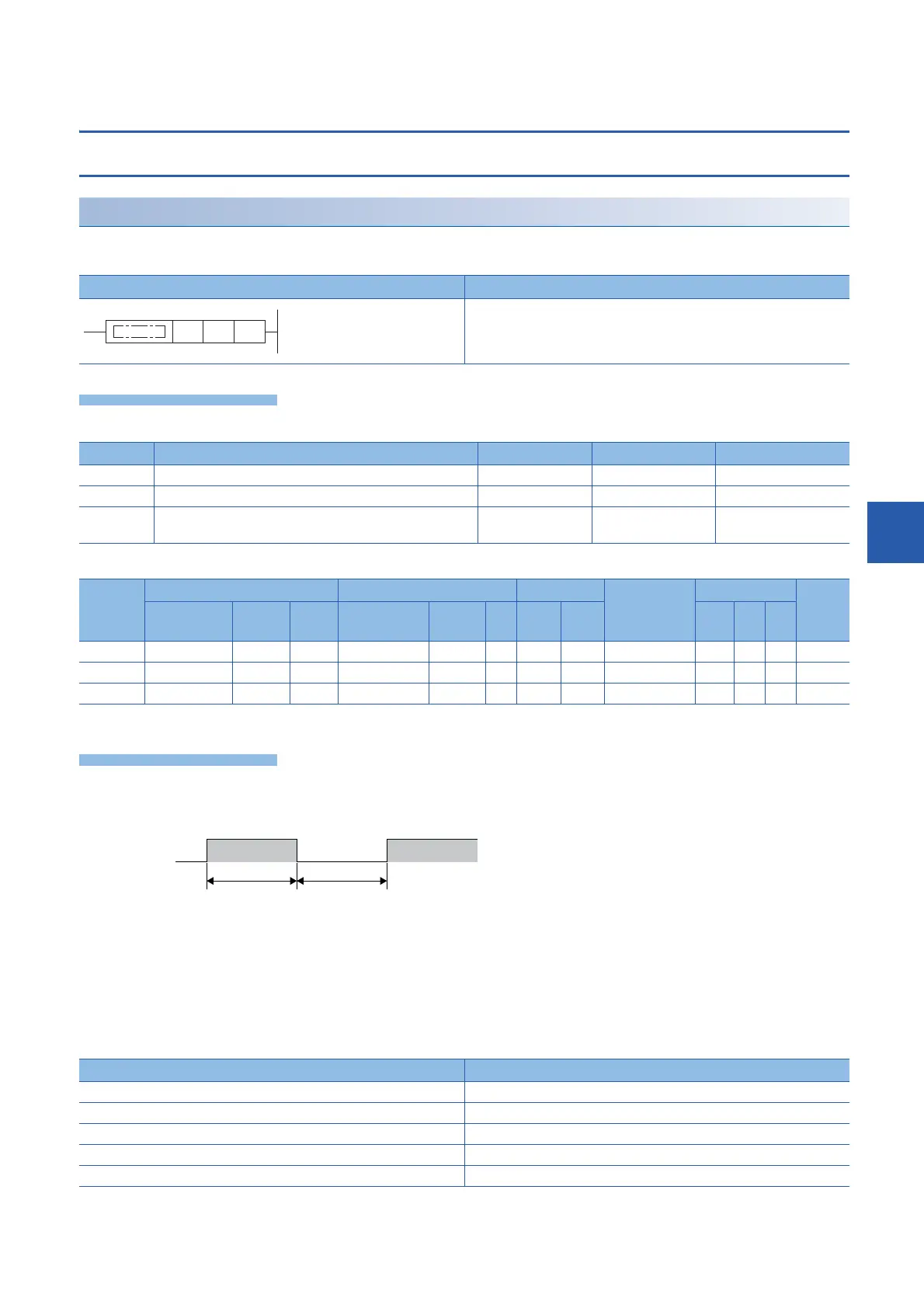
Generating timing pulses
DUTY
This instruction sets user timing clock output destinations (SM420 to SM424 and SM8330 to SM8334) specified by (d) to on
for the number of scans specified by (n1) and to off for the number of scans specified by (n2).
■Descriptions, ranges, and data types
■Applicable devices
*1 Only SM can be used.
• This instruction sets user timing clock output destinations (SM420 to SM424 and SM8330 to SM8334) specified by (d) to on
for the number of scans specified by (n1) and to off for the number of scans specified by (n2).
• Specify SM420 to SM424 (SM8330 to SM8334) in the special relay of the timing clock output destination specified by (d).
• In SM420 to SM424 (SM8330 to SM8334), when one device is turned on, another device is also turned on at the same
time.
• The counted number of scans is stored among SD8330 to SD8334 in accordance with the special relay of the timing clock
output destination specified by (d).
• The counted number of scans stored among SD8330 to SD8334 is reset when the counted value reaches "(n1)+(n2)" or
when the command input (instruction) is set to on.
Ladder diagram Structured text
ENO:=DUTY(EN,s1,s2,d);
Operand Description Range Data type Data type (label)
(n1) Number of scans to be turned on 0 to 65535 16-bit unsigned binary ANY16
(n2) Number of scans to be turned off 0 to 65535 16-bit unsigned binary ANY16
(d) Special relay of the timing clock output destination (SM420 to SM424,
SM8330 to SM8334)
Bit Bit
Operand Bit Word Double word Indirect
specification
Constant Others
X, Y, M, L,
SM, F, B, SB
U\G T, ST,
C, LC
T, ST, C, D,
W, SD, SW, R
U\G Z LC LZ K, H E $
(n1)
(n2)
(d)
*1
Special relay (d) for outputting the timing clock Scan counting device
SM420(SM8330) SD8330
SM421(SM8331) SD8331
SM422(SM8332) SD8332
SM423(SM8333) SD8333
SM424(SM8334) SD8334
OFF
ON
(n1) scans (n2) scans
SM420 to SM424
 Loading...

