680
12 INVERTER COMMUNICATION INSTRUCTION
12.6 Inverter multi command
12.6 Inverter multi command
IVMC
This instruction writes 2 types of settings (operation command and set frequency) to the inverter, and reads 2 types of data
(inverter status monitor, output frequency, etc.) from the inverter at the same time.
■Descriptions, ranges, and data types
*1 Refer to Serial communication manual.
■Applicable devices
*1 T, ST, C cannot be used.
This instruction executes multiple commands of an inverter connected to the channel to be used (n) whose station number is
specified in (s1). Specify the send/receive data type using (s2), the head device which stores data to be written to the inverter
using (s3), and the head device which stores values to be read from the inverter using (d1). For details, refer to Serial
communication manual.
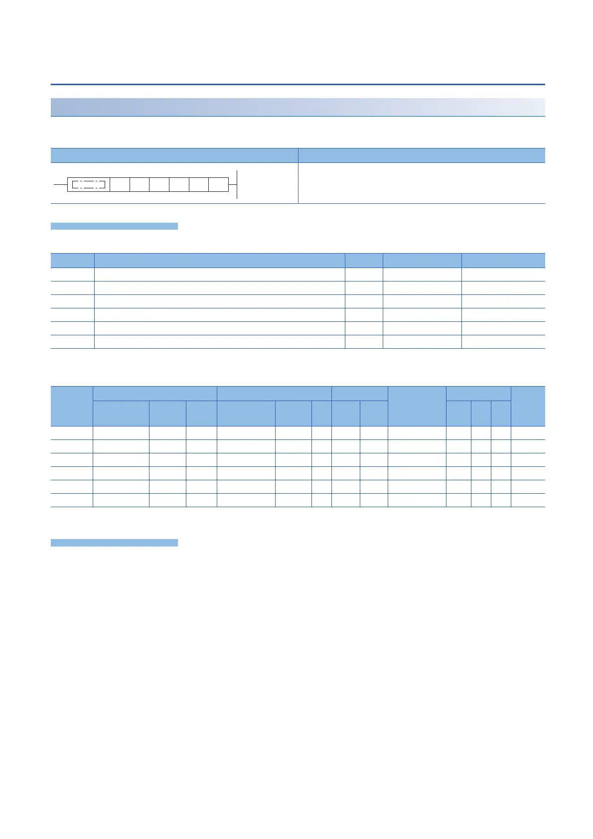
Ladder diagram Structured text
ENO:=IVMC(EN,s1,s2,s3,n,d1,d2);
Operand Description Range Data type Data type (label)
(s1) Inverter station number K0 to 31 16-bit signed binary ANY16
(s2) Multiple instructions for inverter: Send/receive data type specification
*1
16-bit signed binary ANY16
(s3) Head device which stores data to be written to the inverter 16-bit signed binary ANY16
(d1) Head device which stores values to be read from the inverter 16-bit signed binary ANY16
(n) Channel to be used K1 to 4 16-bit unsigned binary ANY16_U
(d2) Head bit device to which the execution status of the instruction is output Bit ANY_BOOL
Operand Bit Word Double word Indirect
specification
Constant Others
X, Y, M, L,
SM, F, B, SB
U\G T, ST,
C, LC
T, ST, C, D,
W, SD, SW, R
U\G Z LC LZ K, H E $
(s1)
*1
(s2)
*1
(s3)
(d1)
(n)
(d2)
*1
(s1) (s2) (s3) (d1) (n) (d2)
 Loading...

