120
5 SEQUENCE INSTRUCTIONS
5.3 Output Instructions
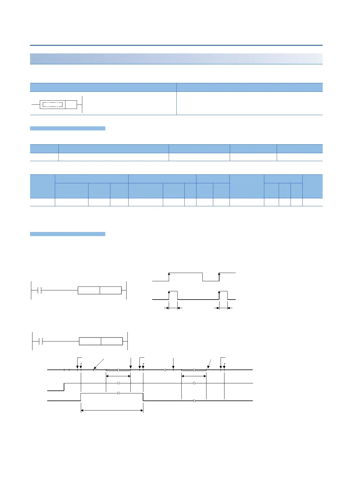
Rising edge output
PLS
This instruction turns ON the device specified by (d) for one scan when the PLS command turns from OFF to ON, and turns
OFF in other cases.
■Descriptions, ranges, and data types
■Applicable devices
*1 Only the FX5 series intelligent function module can be used.
*2 T, ST, C cannot be used.
• This instruction turns ON the specified device for one scan when the PLS command turns from OFF to ON, and turns OFF
in other cases. When there is one PLS instruction programmed for the device specified by (d) during a scan, the specified
device turns ON for one scan.
• If the RUN/STOP/RESET switch is changed from RUN to STOP after execution of the PLS instruction, the PLS instruction
will not be executed even if the switch is set to RUN again.
Ladder diagram Structured text
ENO:=PLS(EN,d);
Operand Remarks Range Data type Data type (label)
(d) Device to be converted to pulse Bit ANY_BOOL
Operand Bit Word Double word Indirect
specification
Constant Others
(DY)
X, Y, M, L,
SM, F, B, SB
U\G T, ST,
C, LC
T, ST, C, D,
W, SD, SW, R
U\G Z LC LZ K, H E $
(d)
*1
*2
(1) 1 scan of PLS M0
(2) CPU module operation stop time
(3) Set the RUN/STOP/RESET switch on the CPU module to RUNSTOP.
(4) Set the RUN/STOP/RESET switch on the CPU module to STOPRUN.
PLS M0
X5
X5 OFF
M0 OFF
ON
ON
1 scan 1 scan
PLS M0
X0
X0 OFF
M0 OFF
ON
PLS M0
LD X0
END0END
PLS M0
LD X0
END
PLS M0
LD X0
0
ON
(1)
(3)
(4)
(3)
(4)
(2)(2)
 Loading...

