542
7 APPLICATION INSTRUCTION
7.15 Drum sequence
Relative method
INCD
This instruction creates many output patterns using a pair of counters.
■Descriptions, ranges, and data types
■Applicable devices
*1 Only C can be used.
*2 T, ST, C cannot be used.
• The current value of a counter is compared with the data table having "n" lines starting from (s1) (which occupies "n" lines
1 device). When the value is equivalent to the table data, the current output is reset, and the next output is controlled. In this
way, the ON/OFF status of specified outputs is controlled in turn.
■Operation example
• The following ladder example shows the operation. (s2) occupies two points. In the following timing chart, C0 and C1
correspond to the two points.
• Suppose that the following data is written in advance by a transfer instruction:
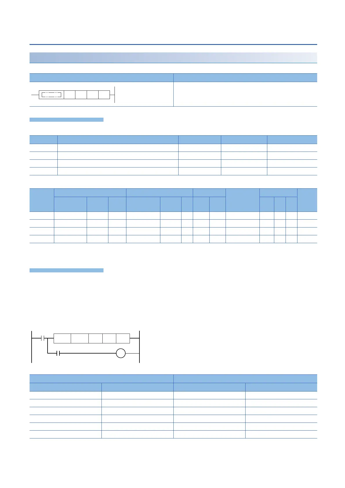
Ladder diagram Structured text
ENO:=INCD(EN,s1,s2,n,d);
Operand Description Range Data type Data type (label)
(s1) Head word device number storing the set value 32-bit signed binary ANY32
(s2) Head counter number for monitoring current value is monitored 32-bit signed binary ANY32
(d) Head bit device number to be output Bit Bit
(n) Number of output bit devices 1 to 64 16-bit signed binary ANY16
Operand Bit Word Double word Indirect
specification
Constant Others
X, Y, M, L,
SM, F, B, SB
U\G T, ST,
C, LC
T, ST, C, D,
W, SD, SW, R
U\G Z LC LZ K, H E $
(s1)
(s2)
*1
(d)
*2
(n)
Device storing data Output
Data value (example) Example
(s1) D300=20 (d) M0
(s1)+1 D301=30 (d)+1 M1
(s1)+2 D302=10 (d)+2 M2
(s1)+3 D303=40 (d)+3 M3
(s1)+(n)-1 (d)+(n)-1
INCD
SM412
C0
K9999
D300 C0 M0 K4
X0
1 sec clock
 Loading...

