Training Guide Course No. 196514
Level 2 Maintenance, X-1000 Series Dispensing Systems 4-8 P/N 196515 (Revision A)
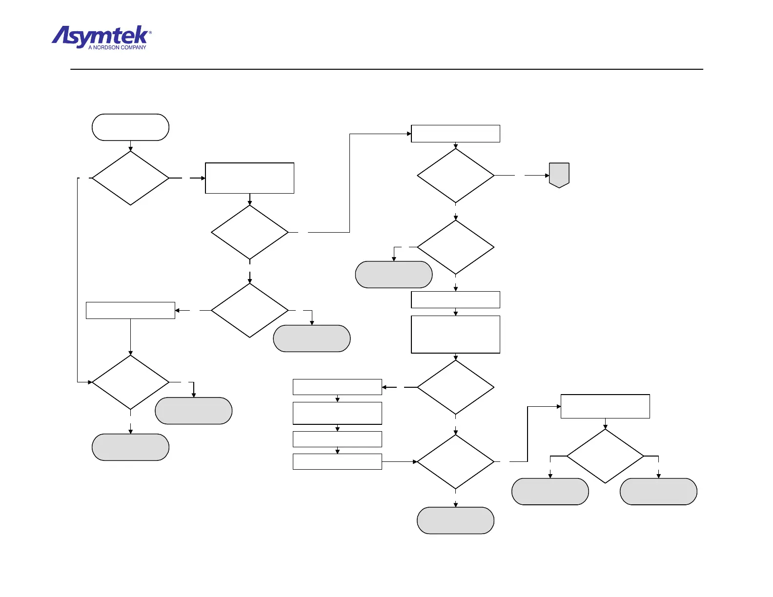
Computer Power Cable
(P/N 193949) has failed.
Is the Power Manager
Fan functioning?
Confirm that the facility power is
connected to the dispensing
system and the Main Circuit
Breaker is in the ON (l) position.
Resolve facility power
A
Verify Main Circuit Breaker
on the Power Manager is
ON (I)
Is the Power Manager
Fan functioning?
Is there 208 to 240
VAC at the facility
power outlet?
Connect the System Power
Cable to the facility power outlet.
No
Yes
No
No
Is there 208 to 240
VAC at the Cable
Connector?
Power Manager
(P/N 62-1620-01) has
failed
System Power Cable
P/N 06-4500-00, US, or
P/N 06-4501-00) has
failed.
Yes
No
Yes
Confirm the Computer Power
Switch is in the ON (I) position.
With computer
power switch ON (I),
is the green power
LED illuminated?
Is computer
power cable securely
connected to unswitched
Power Manager Outlet
AC1 or AC2
Correctly install Power
Cable
No
Open the Lower Front Cabinet
and Computer Doors.
Locate the Computer Passive
Backplane located on the right
inside wall of the Computer.
Locate four red LEDs labeled -
5V, +5V, -12V, and +12V.
Yes
Are the LEDs
illuminated?
Switch the Main Circuit Breaker
to the OFF (0) position.
Disconnect the Computer Power
Cable (P/N 193949) from Power
Manager AC outlet AC1.
Verify that 208 to 240 VAC is
at the AC1 outlet.
Switch the Main Circuit Breaker
to the ON (I) position.
Does the outlet AC1
have 208 to 240 VAC?
Power Manager
(P/N 62-1620-01) has
failed.
No
Yes
No
Check the continuity of the
Computer Power Cable (P/N
193949).
Does the Computer
Power Cable have
continuity?
No
Computer
(P/N 62-1632-00) has
failed.
Yes
Yes No
Yes
Yes
Computer Power Cable
(P/N 193949) has failed.
Is the Power Manager
Fan functioning?
Is the Power Manager
Fan functioning?
Confirm that the facility power is
connected to the dispensing
system and the Main Circuit
Breaker is in the ON (l) position.
Resolve facility power
A
Verify Main Circuit Breaker
on the Power Manager is
ON (I)
Is the Power Manager
Fan functioning?
Is the Power Manager
Fan functioning?
Is there 208 to 240
VAC at the facility
power outlet?
Is there 208 to 240
VAC at the facility
power outlet?
Connect the System Power
Cable to the facility power outlet.
No
Yes
No
No
Is there 208 to 240
VAC at the Cable
Connector?
Is there 208 to 240
VAC at the Cable
Connector?
Power Manager
(P/N 62-1620-01) has
failed
System Power Cable
P/N 06-4500-00, US, or
P/N 06-4501-00) has
failed.
Yes
No
Yes
Confirm the Computer Power
Switch is in the ON (I) position.
With computer
power switch ON (I),
is the green power
LED illuminated?
With computer
power switch ON (I),
is the green power
LED illuminated?
Is computer
power cable securely
connected to unswitched
Power Manager Outlet
AC1 or AC2
Is computer
power cable securely
connected to unswitched
Power Manager Outlet
AC1 or AC2
Correctly install Power
Cable
No
Open the Lower Front Cabinet
and Computer Doors.
Locate the Computer Passive
Backplane located on the right
inside wall of the Computer.
Locate four red LEDs labeled -
5V, +5V, -12V, and +12V.
Yes
Are the LEDs
illuminated?
Are the LEDs
illuminated?
Switch the Main Circuit Breaker
to the OFF (0) position.
Disconnect the Computer Power
Cable (P/N 193949) from Power
Manager AC outlet AC1.
Verify that 208 to 240 VAC is
at the AC1 outlet.
Switch the Main Circuit Breaker
to the ON (I) position.
Does the outlet AC1
have 208 to 240 VAC?
Does the outlet AC1
have 208 to 240 VAC?
Power Manager
(P/N 62-1620-01) has
failed.
No
Yes
No
Check the continuity of the
Computer Power Cable (P/N
193949).
Does the Computer
Power Cable have
continuity?
Does the Computer
Power Cable have
continuity?
No
Computer
(P/N 62-1632-00) has
failed.
Yes
Yes No
Yes
Yes
Diagram Sheet 4-2-1
Main Power Fault Isolation Procedure – Main Power Verification

 Loading...


