Training Guide Course No. 196514
Level 2 Maintenance, X-1000 Series Dispensing Systems 2-5 P/N 196515 (Revision A)
Diagram Sheet 2-1-1
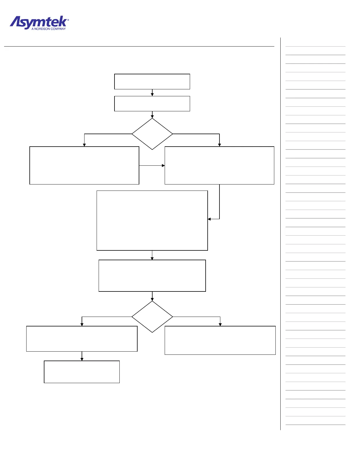
Operations Flow Chart
A part enters the system from an upstream
location
Part is Conveyed to Pre-Dispense Zone
Stop Pins are lowered to stop part transport.
Clamp Bars or Lift Tables raise to hold the part in place.
The underboard heaters turn on and the part is heated to a pre-
programmed temperature. The part remains at the pre-dispense
station for a pre-programmed period of time.
Part is Conveyed to Dispense Zone
Stop Pins are lowered to stop part transport.
Lift Tables/Clamp Bars are raised to hold the part in place during
the dispensing process.
Another part is loaded into the Pre-dispense Station (optional).
A part sensor detects part and the part is
indexed
Dispensing Preparations are Performed
If required, the part is heated to a pre-programmed temperature
by Dispense Station underboard heaters.
The Dispense Head moves to the Purge Station and the
Dispense Valve purges.
If required, fluid may be heated by a Needle Heater (DV-7000 and
DP-3000 Valves) or a heater built into the Valve (DJ-2000).
The Vision System locates master fiducials on the part. Fiducials
are located as reference points for the dispensing patterns.
The Height Sensor probe is lowered to establish a Z-axis datum.
This
rovides information for settin
the dis
ense
a
in FmNT.
The pa
t is Conveyed into the Post-dispense Zone
Stop Pins are lowered to stop part transport.
Lift Tables/Clamp Bars are raised to hold the part in place.
Fluid is Dispensed
Fluid is dispensed onto the part according to a pre-
programmed dispensing pattern
When dispensing is complete, Stop Pins are raised, Lift
Tables/Clamp Bars are lowered.
Part is Conveyed to Downstream Machine or Unloade
The dispensing system can be programmed to move the part
directly to a downstream machine or onto an unloader.
Stop Pins and Clamp Bars or Lift Tables release the part and it is
conve
ed out of the s
stem
Part Exits System
• When dispensing is complete, Stop Pins
and Clamp Bars or Lift Tables release the
part and it is conveyed out of the system.
Pre-
Dispense
Zone?
Ye
No
Post-
Dispense
Zone?
Ye
No

 Loading...


