Training Guide Course No. 196514
Level 2 Maintenance, X-1000 Series Dispensing Systems 4-27 P/N 196515 (Revision A)
With Front Hatch closed,
measure VDC between
Pin 3 and Pin 4.
Is the reading greater
than 23 VDC?
Main Interface PWA
(P/N 60-1200-00) has
failed.
Press the black OFF (0) button
on the Operator's Console and
switch the Main Circuit Breaker
to the OFF (0) position.
Disconnect the Beacon Cable
(P/N 06-4538-00) from J4 on
the XY Servo Interface PWA.
Is the reading greater
than 23 VDC?
Light Beacon (P/N
194035) has failed.
Servo Signal Interconnect
Cable B (P/N 06-4525-00)
has failed.
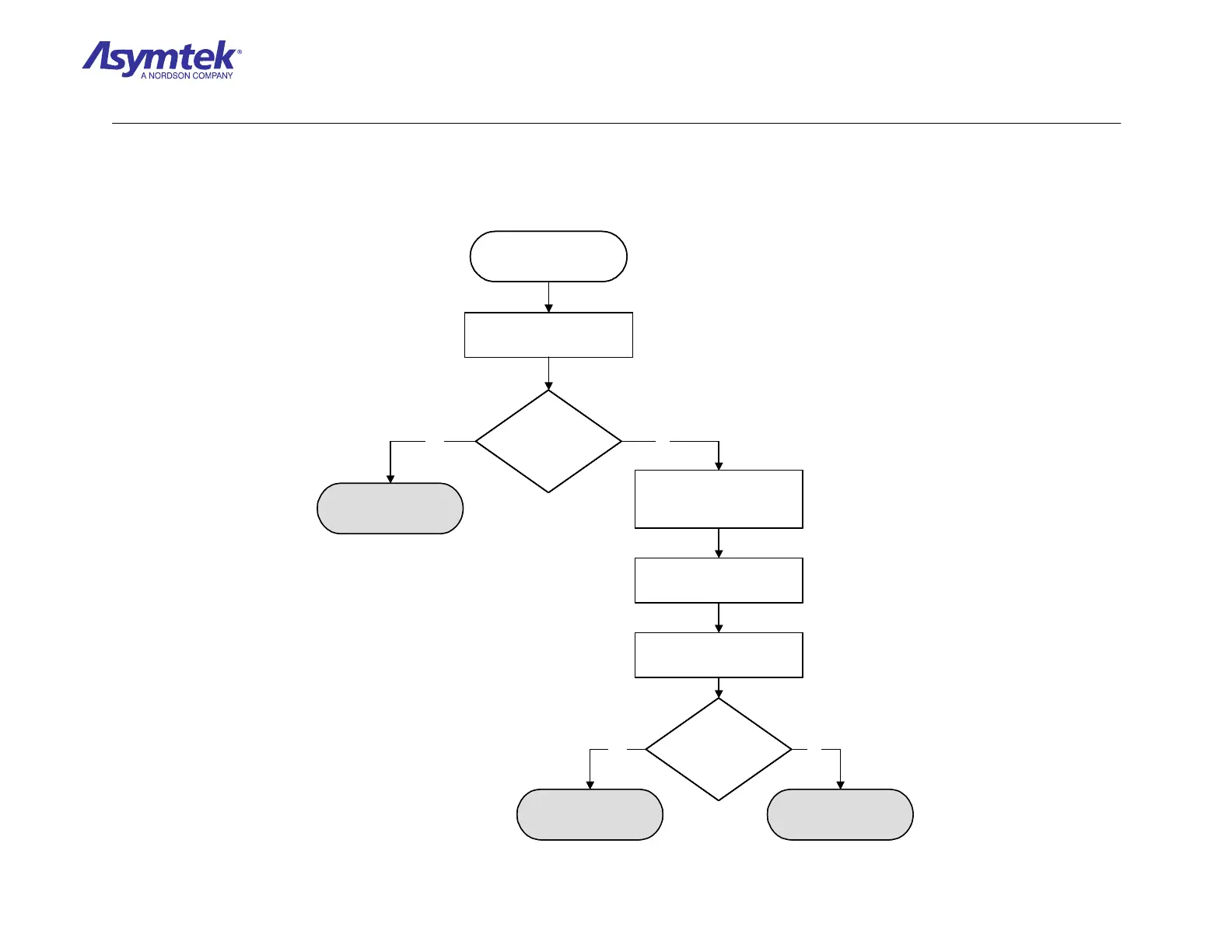
Locate U6 on the Main
Interface PWA.
With the Front Hatch closed,
measure VDC between
Pin 1 and Pin 4.
Yes No
Yes No
With Front Hatch closed,
measure VDC between
Pin 3 and Pin 4.
Is the reading greater
than 23 VDC?
Is the reading greater
than 23 VDC?
Main Interface PWA
(P/N 60-1200-00) has
failed.
Press the black OFF (0) button
on the Operator's Console and
switch the Main Circuit Breaker
to the OFF (0) position.
Disconnect the Beacon Cable
(P/N 06-4538-00) from J4 on
the XY Servo Interface PWA.
Is the reading greater
than 23 VDC?
Is the reading greater
than 23 VDC?
Light Beacon (P/N
194035) has failed.
Servo Signal Interconnect
Cable B (P/N 06-4525-00)
has failed.
Locate U6 on the Main
Interface PWA.
With the Front Hatch closed,
measure VDC between
Pin 1 and Pin 4.
Yes No
Yes No
Diagram Sheet 4-2-20
Interlock Fault Isolation Procedure - Light Beacon Signal Verification

 Loading...


