Training Guide Course No. 196514
Level 2 Maintenance, X-1000 Series Dispensing Systems 4-48 P/N 196515 (Revision A)
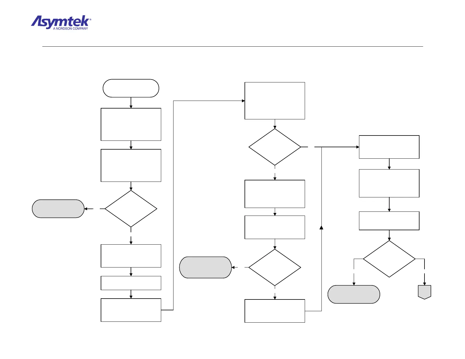
Is the reading 67.5 ±2
VDC for each blue
wire?
XY Servo Interface PWA
(P/N 60-1211-00) has
failed
Confirm there are two blue
wires attached to the J3
connector labeled Servo DC
Power Entry (the positions of
these wires are labeled
+Servo).
Measure VDC at the
connector where each of the
two blue wires come into
J3 (Use TP1 labeled
Servo_Return on XY Servo
Interface PWA for ground).
Press black OFF (0) button
on the Operator’s Console
and switch Main Circuit
Breaker to OFF (0) position.
Locate the Servo
Transformer on Servo Shelf.
Check continuity of the two 8
Amp fuses in the Fuse Tray
on the Servo Transformer AC
Power inlet. The outward
fuse is a spare and the
inward fuse is connected to
the circuit.
Disconnect the Servo AC
Power Cord (P/N 56-0304-
00) from the Servo
Transformer AC Power inlet.
Is there continuity on
both fuses?
Replace fuse (P/N 55-5392).
Reconnect the Servo AC
Power Cord (P/N 56-0304-
00) to the Servo Transformer
AC POWER inlet.
Switch Main Circuit Breaker
to the ON (I) position and
press the green ON (I) button
on the Operator’s Console.
Is the green +SERVO
LED illuminated?
The fuse is root cause of
fault. If it continues, go to
Servo Amplifier Verification
Procedure
Disconnect the Servo AC
Power Cord (P/N 56-0304-
00) from Power Manager
outlet AC3.
Press the black OFF (0)
button on Operator’s Console
and switch Main Circuit
Breaker to OFF (0) position.
Switch the Main Circuit
Breaker to ON (I) position
and press green ON (I)
button on Operator’s
Console.
Measure the VAC coming
from the Power Manager
outlet AC3.
Is the reading between
208 and 240 VAC?
Power Manager (P/N 62-
1620-01) has failed.
A
On the XY Servo Interface
PWA, locate the J3
connector.
No Yes
No
Yes
No
Yes
No
Yes
Diagram Sheet 4-4-6
XY Servo Amplifier Fault Isolation Procedure - Servo Power Verification

 Loading...


