Training Guide Course No. 196514
Level 2 Maintenance, X-1000 Series Dispensing Systems 4-137 P/N 196515 (Revision A)
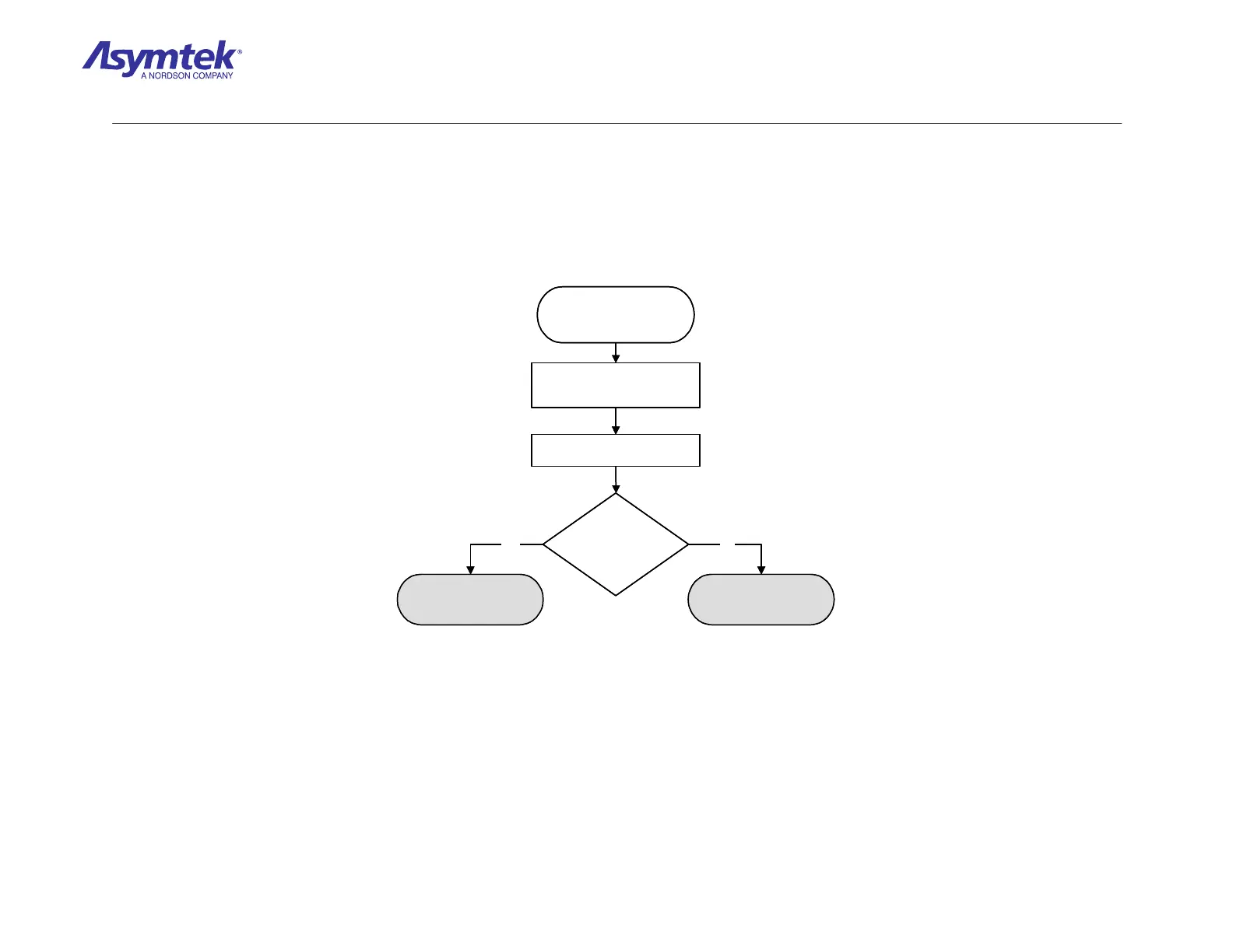
Switch Main Circuit Breaker
to
ON (I) position.
Are the green +5V,
+12V, -12V, and A+5V
LEDs illuminated?
Press the green ON (I) button on
the Operator’s Console, and
enter FmNT.
Locate the power LEDs on the
Main Interface PWA.
Go to Tactile Sensor or
Needle Sensor Verification
Go to System Power Fault
Isolation Procedure
NoYes
Diagram Sheet 4-11-1
Needle Sensor/Tactile Sensor Fault Isolation Procedure – Dispensing Calibration Module Verification

 Loading...


