Training Guide Course No. 196514
Level 2 Maintenance, X-1000 Series Dispensing Systems 4-141 P/N 196515 (Revision A)
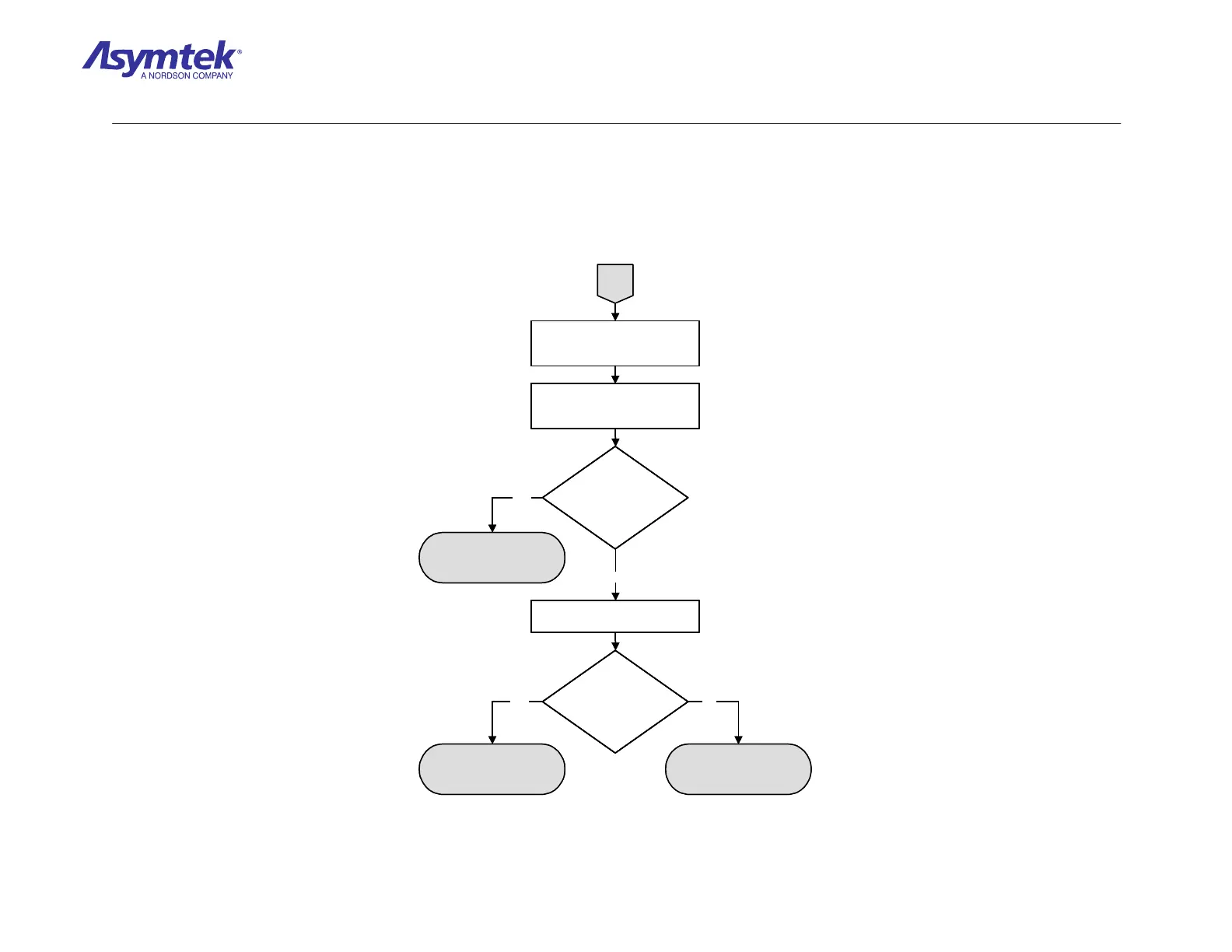
Locate backside of J24 on the
Main Interface PWA labeled
NEEDLE SENSORS.
Measure VDC between Pin 3
and Pin 2 on J24 while toggling
the Needle Sensor.
Does the signal
change from 24 VDC
to 0 VDC?
Check Cable (P/N 06-4599-00)
for continuity (Pinout is 1 to 1).
A
Main Interface PWA (P/N
60-1200-00) has failed.
Does the cable have
continuity?
Needle Sensor Cable (P/N
06-4599-00) has failed.
Needle Sensor (P/N 62-
1617-00) has failed.
Yes No
No
Yes
Locate backside of J24 on the
Main Interface PWA labeled
NEEDLE SENSORS.
Measure VDC between Pin 3
and Pin 2 on J24 while toggling
the Needle Sensor.
Does the signal
change from 24 VDC
to 0 VDC?
Does the signal
change from 24 VDC
to 0 VDC?
Check Cable (P/N 06-4599-00)
for continuity (Pinout is 1 to 1).
A
Main Interface PWA (P/N
60-1200-00) has failed.
Does the cable have
continuity?
Does the cable have
continuity?
Needle Sensor Cable (P/N
06-4599-00) has failed.
Needle Sensor (P/N 62-
1617-00) has failed.
Yes No
No
Yes
Diagram Sheet 4-11-5
Needle Sensor/Tactile Sensor Fault Isolation Procedure – Needle Sensor Verification (Continued)

 Loading...


