EasyManuals Logo

Nordson Asymtek X-1000 Series User Manual

Nordson Asymtek X-1000 Series
500 pages
To Next Page IconTo Next Page
To Previous Page IconTo Previous Page
Page #473 background imageLoading...
Page #473 background image
Training Guide Course No. 196514
Level 2 Maintenance, X-1000 Series Dispensing Systems 5-27 P/N 196515 (Revision A)
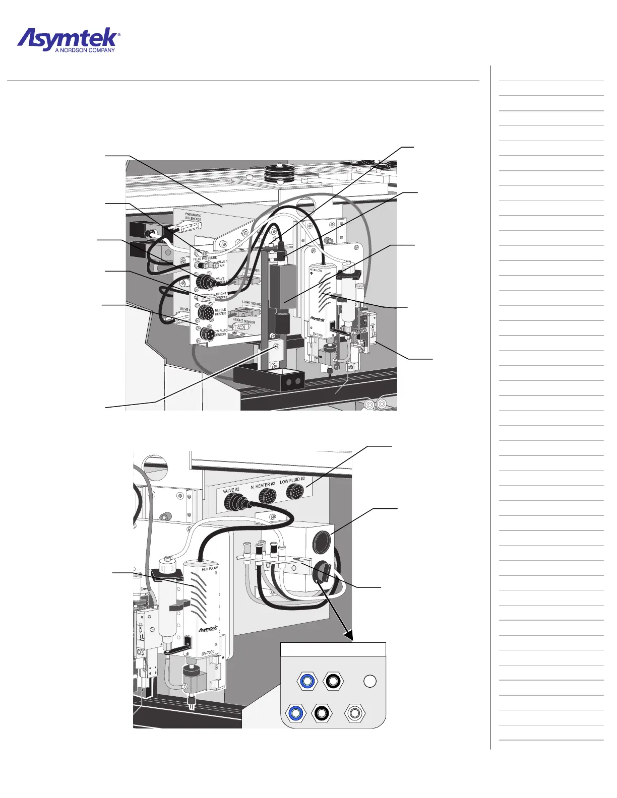
Diagram Sheet 5-5-1
Dispensing Head/Valve Bulkheads
Dispense Hea
d
Controlle
r
Fluid Pressur
e
Pneumatic Hos
e
Valve 1 Powe
r
Cabl
e
Height Senso
r
Power Cabl
e
Valve 1
Electrical/Pneumati
c
Bulkhead
Height
Sensor
Dispense Valve
(DV-7000 shown)
Camera
Camera Coaxial
Cable
Vertical Camera
Bracket Screws
Dispensing Head (Front View)
Camera Horizonta
l
Bracket Screw
s
TOGGLE
VALVE #2
FLUID PRESSURE
#2
Top View
V
alve 2 Bulkheads
Valve 2 Pneumatic
Bulkhead
Counterbalance
Cover
Valve 2 Electrical
Bulkhead
Dispensing Valv
e
(DV-7000 shown
as Valve 2)

Table of Contents

Questions and Answers:

Question and Answer IconNeed help?

Do you have a question about the Nordson Asymtek X-1000 Series and is the answer not in the manual?

Nordson Asymtek X-1000 Series Specifications

General IconGeneral
BrandNordson
ModelAsymtek X-1000 Series
CategoryDispenser
LanguageEnglish

Related product manuals