6 - 27
6 Basic Control Functions
AC Servomotors/Servo Drives 1S-series with Built-in EtherCAT® Communications User’s Manual (I586)
6-9 Connecting with OMRON Controllers
6
*1. CJ1W-NC8 uses the latch signals as follows:
External Latch Input 1: Origin Input
External Latch Input 2: Interrupt Input
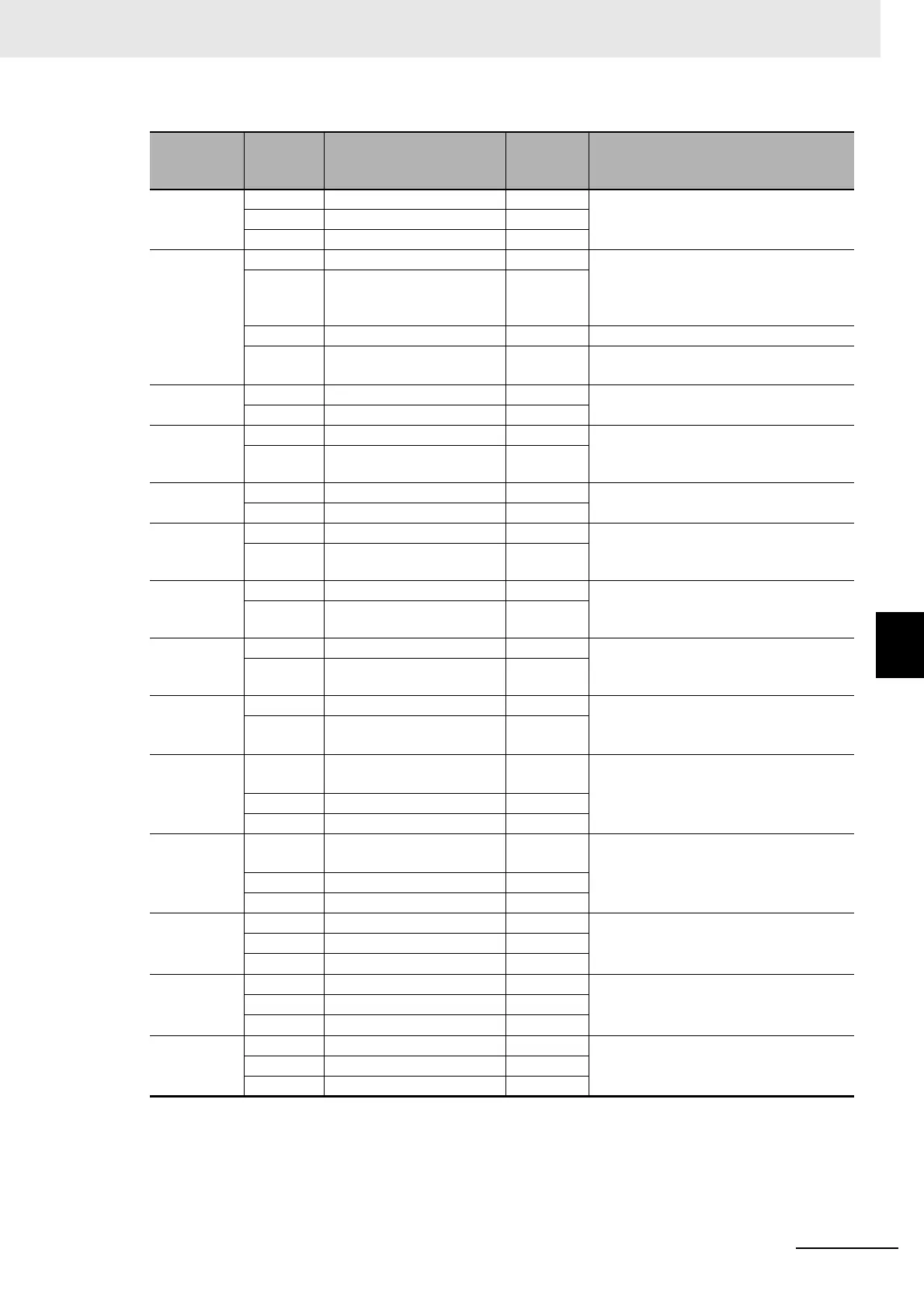
Index (hex)
Subindex
(hex)
Name
Recom-
mended
setting
Description
3001
---
Machine
---
The gear ratio used by the Servo Drive is
8:1, and command units are set by the
controller.
05 Motor Revolutions 8
06 Shaft Revolutions 1
3330
---
Torque Limit
---
If both PCL and NCL are ON, the torque
limit is controlled with the values of 60E0
hex and 60E1 hex that are mapped to a
PDO.
01 Switching Selection 1
05 Positive Torque Limit Value 5,000 Default setting = 500.0%
06 Negative Torque Limit
Value
5,000 Default setting = 500.0%
3A00
---
Homing
---
The value of offset used by the Servo
Drive is 0.
06 Home Offset 0
3B10
---
Drive Prohibition
---
Drive prohibition input is disabled for the
Servo Drive, and this function is handled
by the controller.
01 Enable 0
3B11
---
Software Position Limit
---
Disabled in both positive and negative
directions.
01 Enable Selection 0
3B30
---
Touch Probe 1
---
Touch probe1 source is set to External
Latch Input 1, and Touch probe 2 source
is set to External Latch Input 2.
01 Touch Probe 1 Source 1
3B31
---
Touch Probe 2
---
Touch probe1 source is set to External
Latch Input 1, and Touch probe 2 source
is set to External Latch Input 2.
01 Touch Probe 2 Source 2
4020
---
Warning Customization
---
The warning is automatically cleared
when the cause of the warning is elimi-
nated.
04 Warning Hold Selection 0
4510
---
Encoder
---
Used as the absolute encoder and the
Absolute Encoder Counter Overflow is
ignored.
01 Operation Selection when
Using Absolute Encoder
2
4630
---
Positive Drive Prohibition
Input
---
The Positive Drive Prohibition Input is
allocated to General Input 2 (IN2) with
negative logic (NC contact).
01 Port Selection 2
02 Logic Selection 1
4631
---
Negative Drive Prohibition
Input
---
The Negative Drive Prohibition Input is
allocated to General Input 3 (IN3) with
Negative logic (NC contact).
01 Port Selection 3
02 Logic Selection 1
4632
---
External Latch Input 1
---
The External Latch Input 1 is allocated to
General Input 7 (IN7) with positive logic
(NO contact).
*1
01 Port Selection 7
02 Logic Selection 0
4633
---
External Latch Input 2
---
The External Latch Input 2 is allocated to
General Input 8 (IN8) with positive logic
(NO contact).
*1
01 Port Selection 8
02 Logic Selection 0
4634
---
Home Proximity Input
---
The Home Proximity Input is allocated to
General Input 4 (IN4) with positive logic
(NO contact).
01 Port Selection 4
02 Logic Selection 0

 Loading...

