1 Features and System Configuration
1 - 14
AC Servomotors/Servo Drives 1S-series with Built-in EtherCAT® Communications User’s Manual (I586)
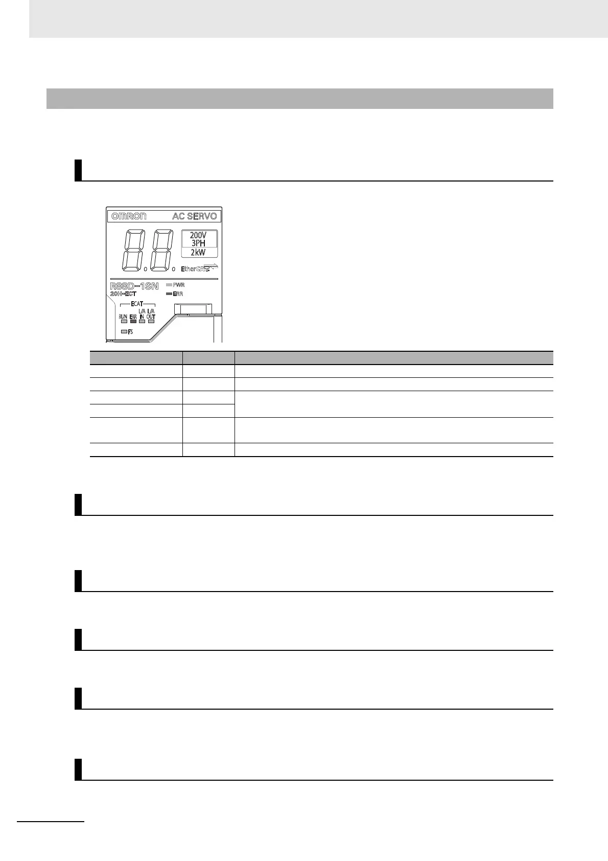
The functions of each part of the Servo Drive are described below.
The following seven indicators are mounted.
For details on display, refer to 5-1-2 Status Indicators on page 5-3.
A 2-digit 7-segment LED display shows error numbers, the Servo Drive status, and other information.
Refer to 10-2-3 Checking the Displays on page 10-5 for details.
Two rotary switches (0 to F hex) are used to set the EtherCAT node address.
Lights when the main circuit power supply carries electric charge.
Used for command input signals, I/O signals, and as the safety device connector. The short-circuit wire
is installed on the safety signals before shipment.
Connector for the encoder installed in the Servomotor.
1-3-2 Servo Drive Functions
Status Indicators
Name Color Description
PWR Green Displays the status of control power supply.
ERR Red Gives the Servo Drive error status.
ECAT-RUN Green Displays the EtherCAT communications status.
ECAT-ERR Red
ECAT-L/A IN,
ECAT-L/A OUT
Green Lights or flashes according to the status of a link in the EtherCAT physical
layer.
FS Red/green Displays the safety communications status.
7-segment LED Display
ID Switches
Charge Lamp
Control I/O Connector (CN1)
Encoder Connector (CN2)

 Loading...

