8 Safety Function
8 - 4
AC Servomotors/Servo Drives 1S-series with Built-in EtherCAT® Communications User’s Manual (I586)
8-2 STO Function via Safety Input Signals
This section explains how to use the STO function via the safety input signals.
The following I/O signals are available to use the STO function: the safety input signals (SF1 and SF2)
and the external device monitoring (EDM) output signal.
Refer to
3-1-5 Control I/O Connector (CN1) Specifications on page 3-27 for I/O signal connection and
external signal processing.
Two safety input circuits are installed to operate the STO function.
• When safety input 1 or 2 turns OFF, the STO function will start operating within 5 ms after the input,
and the motor output torque will be cut off.
• Connect the equipment so that the safety input circuit turns OFF when the STO function is activated.
• Set the operation when the safety input turns OFF in the Stop Selection – Shutdown Option Code
(3B20-01 hex).
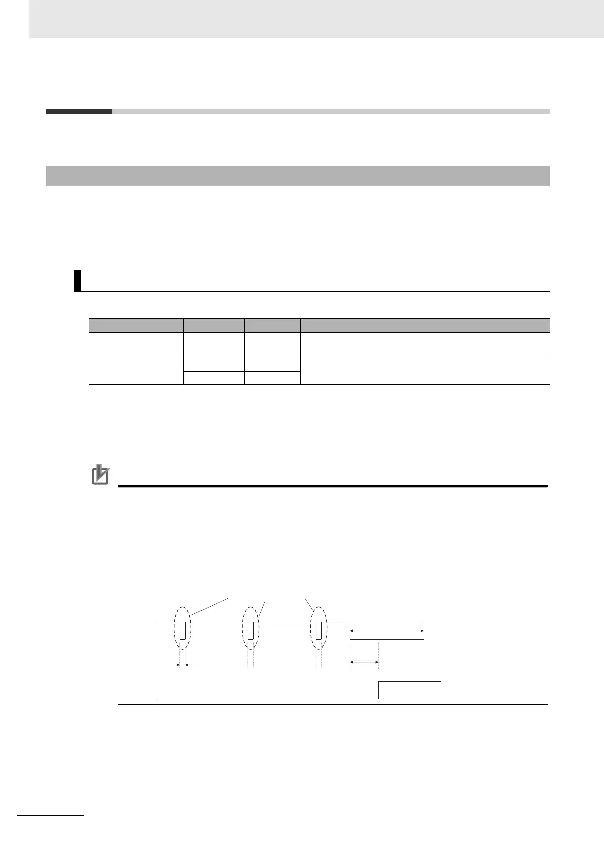
Precautions for Correct Use
L pulses for self-diagnosis of safety equipment
When you connect a safety device, such as a safety controller or a safety sensor, the safety
output signal of the device may include L pulses for self-diagnosis. To avoid malfunction due to
the L pulses for self-diagnosis, a filter that removes the L pulses is built into the safety input cir-
cuit. If the OFF time of the safety input signal is 1 ms or less, the safety input circuit does not
recognize it as OFF. To make sure that OFF is recognized, maintain the OFF status of safety
input signal for at least 5 ms.
8-2-1 I/O Signal Specifications
Safety Input Signals
Signal Symbol Pin No. Description
Safety input 1 SF1+ CN1-3,23 The upper arm drive signal of the power transistor inside the
Servo Drive is cut off.
SF1- CN1-4,24
Safety input 2 SF2+ CN1-5,25 The lower arm drive signal of the power transistor inside the
Servo Drive is cut off.
SF2- CN1-6,26
For self-diagnosis L pulse
1 ms or less
5 ms or less
Normal operation
STO status
Safety
Input signal
Servo Drive
operation
5 ms or more

 Loading...

