6 - 25
6 Basic Control Functions
AC Servomotors/Servo Drives 1S-series with Built-in EtherCAT® Communications User’s Manual (I586)
6-9 Connecting with OMRON Controllers
6
6-9 Connecting with OMRON Controllers
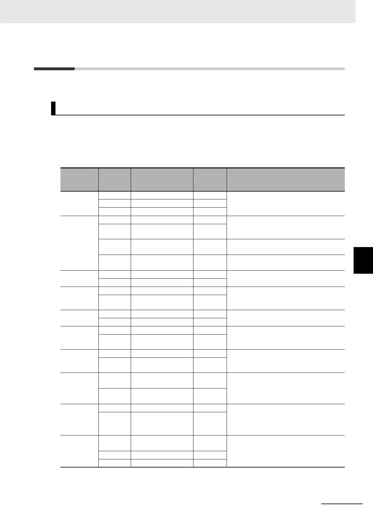
This section describes the settings required to connect the Servo Drive with an OMRON controller.
The following tables show the setting values required to use the control functions of the controller.
If you change these settings, read and understand the relevant specifications in advance and set
appropriate values.
Common Settings
Machine Automation Controller NJ/NX-series CPU Unit
Index (hex)
Subindex
(hex)
Name
Recom-
mended
setting
Description
3001
---
Machine
---
The gear ratio used by the Servo Drive is 1:1,
and command units are set by the control-
ler.
*1
05 Motor Revolutions 1
06 Shaft Revolutions 1
3330
---
Torque Limit
---
If both PCL and NCL are OFF, the torque limit
is controlled with the values of 60E0 hex and
60E1 hex that are mapped to a PDO.
01 Switching Selection 2
05 Positive Torque Limit
Value 2
5,000 Default setting = 500.0%
06 Negative Torque Limit
Value 2
5,000 Default setting = 500.0%
3A00
---
Homing
---
The value of offset used by the Servo Drive is
0.
06 Home Offset 0
3B10
---
Drive Prohibition
---
Drive prohibition input is disabled for the
Servo Drive, and this function is handled by
the controller.
01 Enable 0
3B11
---
Software Position Limit
---
Disabled in both positive and negative direc-
tions.
01 Enable Selection 0
3B30
---
Touch Probe 1
---
Touch probe1 source is set to External Latch
Input 1, and Touch probe 2 source is set to
External Latch Input 2.
01 Touch Probe 1 Source 1
3B31
---
Touch Probe 2
---
Touch probe1 source is set to External Latch
Input 1, and Touch probe 2 source is set to
External Latch Input 2.
01 Touch Probe 2 Source 2
4020
---
Warning Customiza-
tion
---
The warning is automatically cleared when
the cause of the warning is eliminated.
04 Warning Hold Selec-
tion
0
4510
---
Encoder
---
Used as the absolute encoder and the Abso-
lute Encoder Counter Overflow is ignored.
01 Operation Selection
when Using Absolute
Encoder
2
4630
---
Positive Drive Prohibi-
tion Input
---
The Positive Drive Prohibition Input is allo-
cated to General Input 2 (IN2) with negative
logic (NC contact).
01 Port Selection 2
02 Logic Selection 1

 Loading...

