4 - 77
4 Configuration and Wiring
AC Servomotors/Servo Drives 1S-series with Built-in EtherCAT® Communications User’s Manual (I586)
4-4 Regenerative Energy Absorption
4
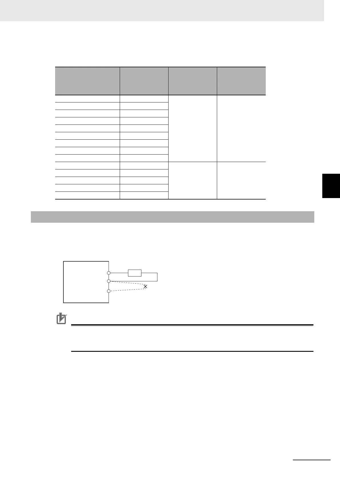
4-4-4 Connecting an External Regeneration Resistor
External Regeneration Resistance Unit
R88A-RR1K6, R88A-RR550
Normally, short-circuit B2 and B3.
When an External Regeneration Resistor is required, remove the short-circuit wire between B2 and B3,
and connect an External Regeneration Resistor between B1 and B2 as shown below.
Precautions for Correct Use
In Regeneration (4310 hex), set a value which is appropriate for the external regeneration
resistor that is connected. If you set a wrong value, the resistor may produce heat abnormally,
and fire or burning may result.
Model Resistance value
Power to be
absorbed for
120°C tempera-
ture rise
Heat radiation
specification
R88A-RR1K602R5 2.5 Ω 640 W Forced cooling by
the fan
R88A-RR1K604 4 Ω
R88A-RR1K605R4 5.4 Ω
R88A-RR1K610 10 Ω
R88A-RR1K616 16 Ω
R88A-RR1K617 17 Ω
R88A-RR1K620 20 Ω
R88A-RR1K640 40 Ω
R88A-RR1K666 66 Ω
R88A-RR55002R5 2.5 Ω 110 W Natural cooling
R88A-RR55004 4 Ω
R88A-RR55005R4 5.4 Ω
R88A-RR55010 10 Ω
R88A-RR55016 16 Ω
4-4-4 Connecting an External Regeneration Resistor
Servo Drive
B1
B2
External Regeneration
Resistor
Remove the short-circuit wire
between B2 and B3.
B3

 Loading...

