13 - 5
13 Maintenance and Inspection
AC Servomotors/Servo Drives 1S-series with Built-in EtherCAT® Communications User’s Manual (I586)
13-4 Method for Broken Ring Maintenance and Inspection
13
13-4 Method for Broken Ring Maintenance
and Inspection
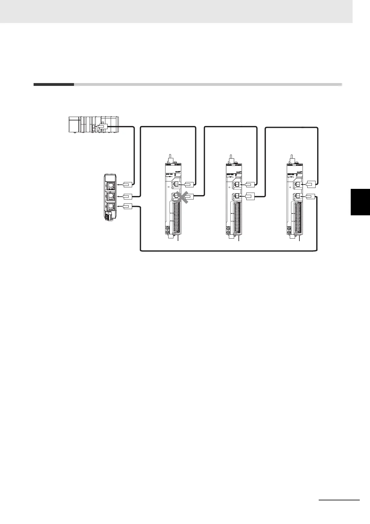
This section takes the following example of a configuration in which the ring is broken between Servo
Drive A and B, and describes how to perform inspection and how to replace the Servo Drive.
1 Identify where the ring is broken.
• With a tool such as support software, find the node address of the Servo Drive breaking the
ring. For the NJ/NX-series Controller, check the _EC_RingBreakNodeAdr system-defined
variable that will provide you with the node address of Servo Drive A. Check that the L/A OUT
indicator of Servo Drive A and the L/A IN indicator of Servo Drive B are OFF.
2 Reconnect the EtherCAT communications cable between Servo Drive A and B.
• Stop operation and turn OFF the power supply to the EtherCAT master and to the slaves.
• After the charge lamps of Servo Drive A and B turn OFF, reconnect the EtherCAT communi-
cations cable, and then turn ON the control power supply to Servo Drive A and B.
• If the L/A OUT indicator of Servo Drive A and the L/A IN indicator of Servo Drive B are ON,
the ring disconnection status has been fixed.
• If the L/A IN and L/A OUT indicators are OFF, the ring disconnection status has not been fixed
yet. Move on to the next step.
3 Replace the relevant cable with a new EtherCAT communications cable.
• Replace the EtherCAT communications cable between Servo Drive A and B with a new cable.
To avoid incorrect wiring, do not remove any other cable.
• If the L/A OUT indicator of Servo Drive A and the L/A IN indicator of Servo Drive B are ON or
blink, the ring disconnection status has been fixed.
• If the L/A IN and L/A OUT indicators are OFF, Servo Drive A or B is faulty. Move on to the next
step.
4 Identify the faulty Servo Drive.
• As in the following figure, connect one EtherCAT communications cable to the ECAT IN and
ECAT OUT connectors on Servo Drive A. If the L/A IN and L/A OUT indicators remain OFF,
Servo Drive A is faulty.
• In the same way, connect one EtherCAT communications cable to the ECAT IN and ECAT
OUT connectors on Servo Drive B. If the L/A IN and L/A OUT indicators remain OFF, Servo
Drive B is faulty.
L1 L2
L5
L3
Servo Drive A Servo Drive B
L4
Servo Drive C
RUN IN OUT
FS
L/A L/A
ERR
RUN IN OUT
FS
L/A L/A
ERR
RUN IN OUT
FS
L/A L/A
ERR

 Loading...

