3-42
Function No. Name Description Setting
range
Refer-
ence
page
Digital Op-
erator func-
tion selec-
tion
n007 Operation
direction
selection key
permit/inhibit
0: Inhibits Operation Mode Selection Key
from functioning.
1: Permits Operation Mode Selection Key
to function.
0, 1 [1] 3-57
n008 Stop Key func-
tion selection
0: The STOP/RESET Key will function
only when the Inverter is running with
the run command through the Digital
Operator.
1: The STOP/RESET Key will function
anytime.
0, 1 [1] 3-58
n009 Frequency ref-
erence setting
selection
0: Permits frequency reference set with
the Digital Operator to be valid without
Enter Key input.
1: Permits frequency reference set with
the Digital Operator to be valid with En-
ter Key input.
0, 1 [1] 3-58
V/f pattern
selection
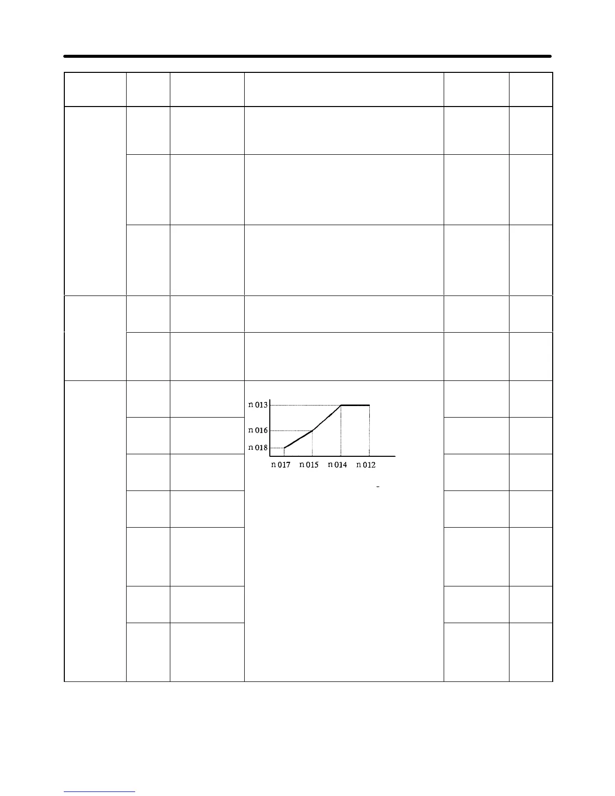
n010 V/f pattern
selection
0to E: Selects from 15 fixed V/f patterns.
F: Selects optional V/f pattern with n012
to n018 settings.
0 to F [1] 3-58
n011 Rated input
voltage of mo-
tor
(see note)
Set rated input voltage of motor with 1 V
units.
150.0 to
255.0
[200.0]
3-60
V/f pattern
selection
n012 Maximum fre-
quency
(FMAX)
Voltage
(V)
50.0 to
400.0 [60.0]
3-60
n013 Maximum volt-
age (VMAX)
(see note)
there is no difference between n015 and
n017 in set value, in which case the set
value of n016 will be ignored.
0.1 to 399.9
[3.0]
3-61
n016 Intermediate
output fre-
quency volt-
age (VC)
(see note)
0.1 to 255.0
[15.0] (See
note 1, 2.)
3-61
n017 Minimum out-
put frequency
(FMIN)
0.1 to 10.0
[1.5]
3-61
n018 Minimum out-
put frequency
voltage
(VMIN)
(see note)
0.1 to 50.0
[10.0] (See
note 1, 2.)
3-61
Note 1. With 400-V Inverters, the setting range upper limits and default settings are double those
shown in the table.
Note 2. The default settings for Inverters of 55 kW or more are as follows:
n016 = 12.0/24.0, n018 = 6.0/12.0
Preparing for Operation Chapter 3
 Loading...


