XtraDrive User Manual Chapter 7: Using the Panel Operator
7-13
Sequence I/O Signal Monitor Display
The following section describes the monitor display for sequence I/O
signals.
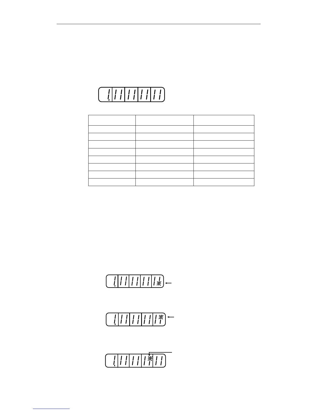
Input Signal Monitor Display
8 7 6 5 4 3 2 1
Top: OFF ("H" level)
Bottom: ON ("L" level)
Number
LED Number Input Terminal Name Default Setting
1 SI0 (CN1-40) /S-ON
2 SI1 (CN1-41) /P-CON
3 SI2 (CN1-42) P-OT
4 SI3 (CN1-43) N-OT
5 SI4 (CN1-44) /ALM-RST
6 SI5 (CN1-45) /P-CL
7 SI6 (CN1-46) /N-CL
8 (CN1-4) SEN
Note: Refer to 5.3.3 Input Circuit Signal Allocation for details on input terminals.
Input signals are allocated as shown above and displayed on the panel
of the servo amplifier or the digital operator. They are indicated by the
ON/OFF status of the vertical parts of the seven-segment displays
located in top and bottom rows. (The horizontal segments are not used
here). These vertical segments turn ON or OFF relative to the state of
the corresponding input signals (ON for “L” level and OFF for “H”
level).
Examples
• When /S-ON signal is ON (Servo ON at “L” signal)
8 7 6 5 4 3 2 1
The bottom segment
of number 1 is lit
• When /S-ON signal is OFF
8 7 6 5 4 3 2 1
The top segment
of number 1 is lit
• When P-OT signal operates (Operates at “H” signal)
8 7 6 5 4 3 2 1
The top segment
of number 3 is lit.