XtraDrive User Manual Chapter 5: Parameter Settings and Functions
5-27
5. Set the parameters.
Reduce the electronic gear ratio to lower terms so that both A and B
are integers smaller than 65535, then set A and B in the respective
parameters:
Pn202 Electronic Gear Ratio (Numerator)
A
B
Pn203 Electronic Gear Ratio (Denominator)
Parameter Signal Setting Control Mode
Pn202
Electronic Gear Ratio
(Numerator)
Range: 1 to 65535
Default Setting: 4
Position Control
Pn203
Electronic Gear Ratio
(Denominator)
Range: 1 to 65535
Default Setting: 1
Position Control
Set the electronic gear ratio according to equipment specifications.
M
Electronic
gear
B
_
A
Motor
Xtra D ri ve
Reference
input pulse
Electronic Gear Ratio =
A
B
=
203Pn
202Pn
• B = [(Number of encoder pulses) × 4] × [motor speed]
• A = [Reference units (travel distance per load shaft revolution)] ×
[load shaft revolution speed]
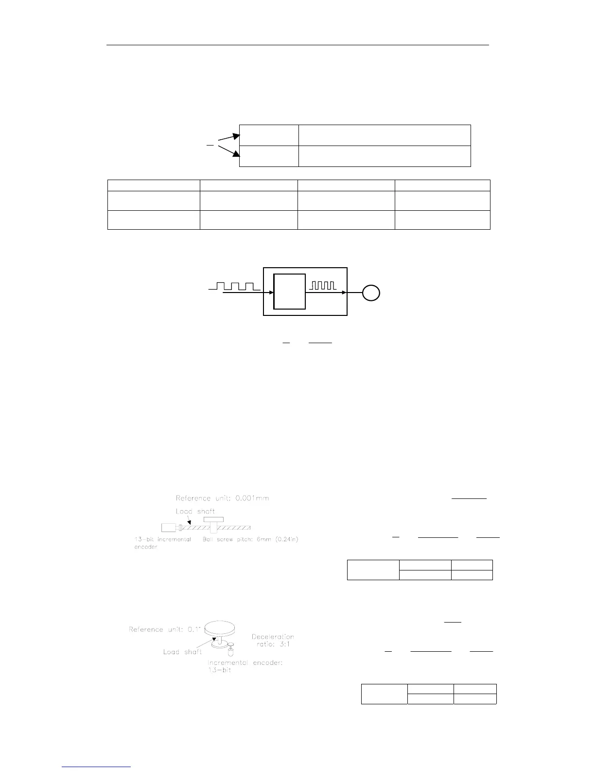
Electronic Gear Setting Examples
The following examples show electronic gear settings for different load
mechanisms.
Ball Screws
Travel distance per load shaft revolution =
in00004.0
in24.0
=
6000
Electronic gear ratio
=
A
B
=
6000
1x 4x 2048
=
203Pn
202Pn
Pn202 8192
Preset
Values
Pn203 6000
Circular Tables
Travel distance per load shaft revolution =
°
°
1.0
360
= 3600
Electronic gear ratio
=
A
B
=
3600
3x 4x 2048
=
203Pn
202Pn
Pn202 24576
Preset
Values
Pn203 3600