Networks
Polycom, Inc. 2–27
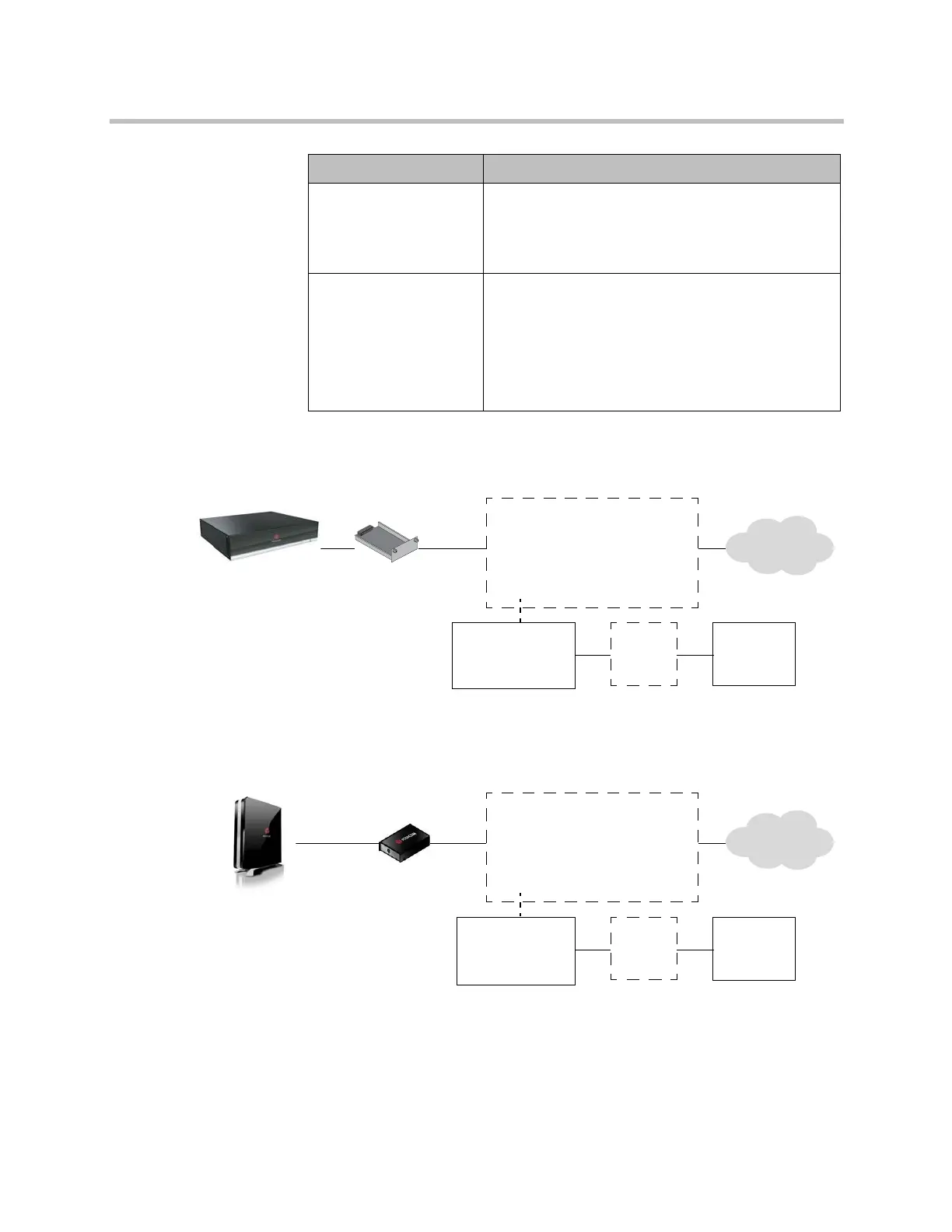
The following diagram shows a general view of how network interface
modules are connected in Polycom HDX 9000 series systems.
The following diagram shows a general view of how network interface
modules are connected with Polycom HDX 8000 series, Polycom HDX 7000
series, and Polycom HDX 4000 series systems.
PRI
(outside North America
and Japan)
• 75 W coaxial adapter, if the network connection is
via a 75 W coaxial cable.
• PBX crossover cable, if required for your PBX.
• PRI line.
Serial
V.35/RS-449/ RS-530
(with RS-366 dialing)
• Third-party network equipment and cables.
Contact your network equipment vendor to obtain the
appropriate cables for the equipment you connect to
this interface. If you use only one cable, connect it to
port 1 of the network interface module and to the
lowest-numbered port of the data communications
equipment.
Network Module Requirements
Additional device
Examples:
Quad BRI — NT-1
PRI — CSU
V.35/RS-449/RS-530 —
encryption equipment
Network
interface
module
External power
supply if using
PRI or NT-1
UPS
Power
source
Network
Polycom HDX
system
+
Additional device
Examples:
Quad BRI — NT-1
PRI — CSU
V.35/RS-449/RS-530 —
encryption equipment
Network
interface
module
External power
supply if using
PRI or NT-1
UPS
Power
source
Network
Polycom HDX
system
Artisan Technology Group - Quality Instrumentation ... Guaranteed | (888) 88-SOURCE | www.artisantg.com