Preparing for Use
R&S
®
SMB100A
23Operating Manual 1407.0806.32 ─ 21
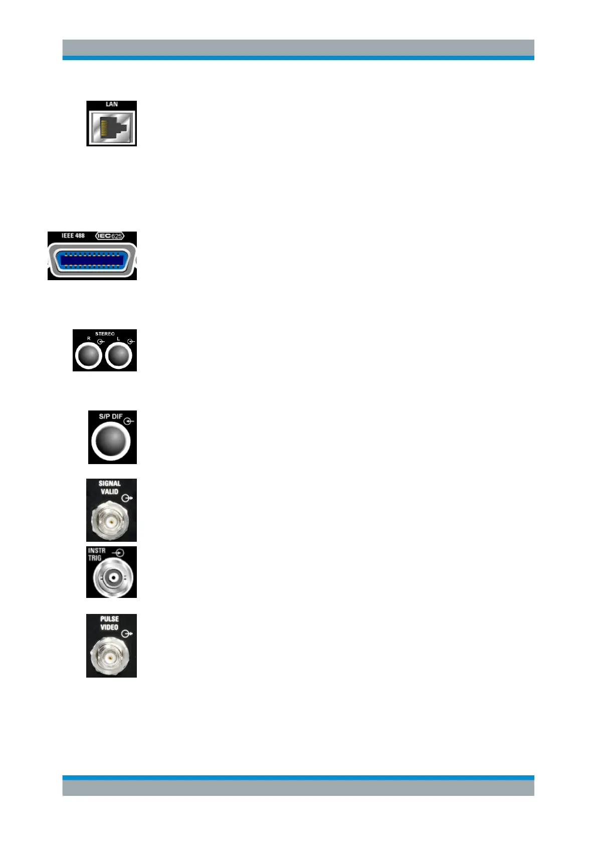
LAN CONNECTOR
Ethernet interface
●
For integrating signal generators in a network
●
Remote control of signal generator
●
Remote access to the signal generator
●
Firmware update
See also:
●
Chapter 2.6, "Setting Up a Network (LAN) Connection", on page 34
●
Chapter 6.1.3, "LAN Interface", on page 237
IEC 625/IEEE 488
IEC-bus (IEEE 488) interface for remote control of the instrument.
See also Chapter A.1, "GPIB Bus Interface", on page 490 and Chapter 6.1.6, "GPIB
Interface (IEC/IEEE Bus Interface)", on page 241.
Note: In order to avoid electromagnetic interference (EMI) caused by open lines,
always terminate any connected IEC-bus cable with an instrument or a controller.
STEREO R/L
Inputs for analog stereo modulation signals. External modulation sources or the inter-
nal LF generator can be used (stereo modulation is available with option R&S SMB-
B5).
See also Chapter 5.4.6, "Stereo Modulation", on page 211.
S/P DIF
Input for digital stereo signals (stereo modulation is available with option R&S SMB-
B5).
See also Chapter 5.4.6, "Stereo Modulation", on page 211.
SIGNAL VALID
Output of valid signal. This signal marks the valid signal times (valid level and fre-
quency indication). The signal is generated automatically.
INSTR TRIG
Input for external trigger for sweeps and list mode.
See also Chapter 5.3.7.4, "List Mode", on page 187 and Chapter 5.3.7.1, "Overview",
on page 174.
PULSE VIDEO
Output of internal pulse generator signal or external pulse signal fed in via the PULSE
EXT connector (video signal).
See alsoChapter 5.4.5, "Pulse Modulation (PM)", on page 209 .
Rear Panel Tour

 Loading...