9. Re-position the side fences [I] [J] ( x 4).
• A4: Outer slot position
• LT: Inner slot position
10. Re-install the DC motor cover and the tray cover.
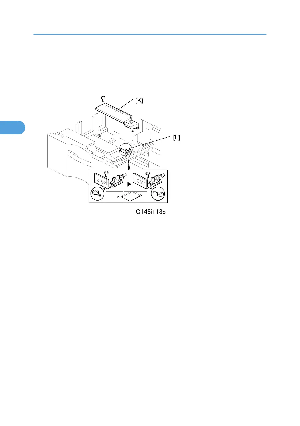
11. Remove the rear bottom plate [K] ( x 1).
12. Re-position the return position sensor bracket [L] ( x 1).
To use the paper tray for A4 size, set the screw in the left hole as shown. (For LT size, the
screw should be placed on the right.)
13. Reinstall the rear bottom plate.
14. Input the new paper size into SP5959-001 (Paper Size – Tray 1). For details, see SP5959 in
section “4. Service Tables”.
15. Do the printer adjustments. See "Print Image Adjustment" at the end of this section.
3. Replacement and Adjustment
214