• Cleaning Roller: About +1.0 kV max. through terminal [D] to the cleaning roller [E].
Drive rollers [F, G] are grounded so that the cleaning unit can clean the belt easily.
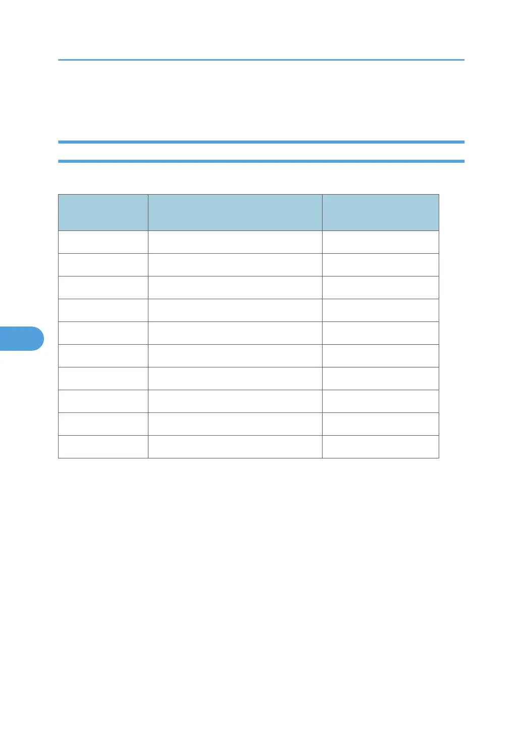
Transfer Current Settings
Here is a list of the default current settings for each paper feed station.
SP No. Station/Mode
Transfer Current (Initial Val-
ue)
SP2301-001 Trays 1, 2, 3: Front Side 80 μA
SP2301-002 Trays 1, 2, 3: Back Side 80 μA
SP2301-004 Postcard: Front Side 165 μA
SP2301-005 Paper Interval 15 μA
SP2301-006 Tab Paper 75 μA
SP2301-007 Thick Paper: Front Side 120 μA
SP2301-008 OHP: Front Side 75 μA
SP2301-009 Tracing Paper: Front Side 120 μA
SP2301-010 Image Leading Edge 65 μA
SP2301-011 Image Trailing Edge 65 μA
The charge for cleaning is applied even during the interval between sheets of copy paper.
The transfer roller output changes to 2.6 kV, and the cleaning roller output is fixed at 1.0 kV:
• When the job ends
• Whenever the drum motor is turning, except during copying and during process control
6. Details
476