14. Connect the HP Sensor 2 harness connector [15] to CN130 of the finisher PCB and to HP
Sensor 2.
15. Connect the single end of the hopper full sensor connector cable [16] to the hopper full sensor
on the arm ( x 1, clamp x 1), then connect the other two connectors to HP Sensor 1 [17]
and CN620 [18] of the punch PCB.
• No special DIP switch settings are required for this punch unit. The punch unit sends an identifi-
cation signal to the machine, so it knows what type of punch unit has been installed.
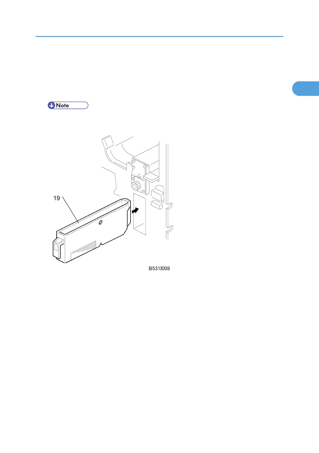
16. Slide the hopper [19] into the finisher.
17. Re-attach the inner cover and rear cover.
18. Close the front door and re-connect the finisher to the machine.
Punch Unit (B531/A812)
77