DISPLAY PANEL MANUAL
16-5
●For example
Sample setting of Device Memory Map to access I/O memory of Read/Write area of the PLC is shown
as below.
PLC : Mitsubishi Q series
Read Area source memory : D00000 - D00002
Read Area transfer timing : Synchronized writing : The data at the source memory address is
transferred to a memory address registered in a device memory map at the
leading edge of the control memory bit (0 to 1). D00100-01 of Control
Memory is target bit in example.
Write Area target memory : D00003 - D00005
Write Area transfer timing : Periodical reading : The memory data registered in a device memory map
is transferred to the target memory address every cycle set at [Reading
Cycle]. Reading cycle is 0.5 sec in example.
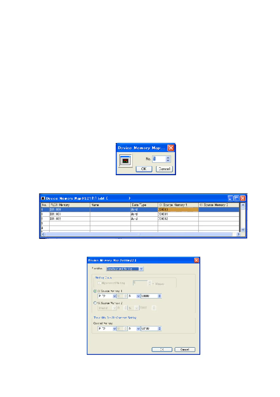
1) Click [System setting] and [Device Memory Map] and [PLC1] to set Read Area.
Figure 16.2-3 Device Memory Map No. Input
2) Input table No. and click [OK] to indicate setting window of Device Memory Map.
Figure 16.2-4 Device Memory Map setting window
3) Input the settings for Device Memory Map.
Figure 16.2-5 Device Memory Map setting for detail