Installing cable fittings
OmniTrax Product Guide Page 121
Installing cable fittings
OmniTrax sensor cables require field-installed TNC connectors and the addition of 10 ferrite beads
on the lead-in section of cable. Field-installed connectors are also required for cable splices and to
repair damaged cable.
Installing ferrite beads
Points to remember
• ferrite beads must be installed before the connectors
• ferrite beads are fragile, do NOT allow them to slide freely and hit each other
• if a bead breaks at any time during the installation, remove it
• a minimum of seven beads are required on each lead-in cable
• hardware bypasses (OC2, SC2) require 20 ferrite beads, 10 on each end
• ferrite beads can be installed in slots, by using a drill to widen the slots at the location of each
bead
• SC2 - 23 mm (7/8 in.)
• OC2 - 3 cm (1 1/8 in.)
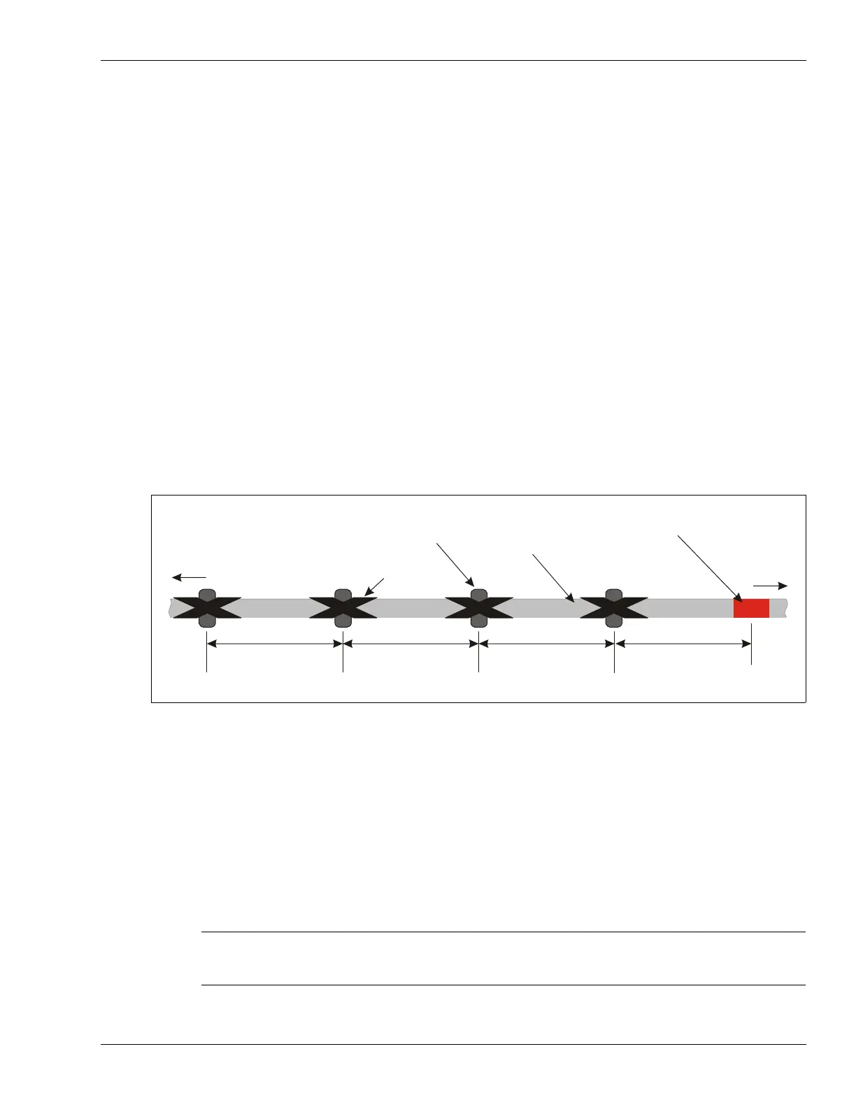
1. Starting at the red band that marks the end of the lead-in cable, and measuring away from the
detecting cable, carefully slide the 10 ferrite bead into the correct positions on the lead-in
cable. The first bead is located on the lead-in cable, 30 cm (12 in.) away from the red band.
2. Space the remaining beads 30 cm (12 in.) apart on the non-detecting cable, and secure the
beads with electrical tape.
Installing connectors on OC2 sensor cable
To install connectors on OC2 sensor cables, you require an OmniTrax connector kit (GT0967) an
OmniTrax cable tool kit (A4KT0200) and a portable heat gun.
Figure 87: Positioning the ferrite beads
Note The OmniTrax connector kits are matched to the OC2 cables. Use
ONLY the supplied connectors and the specified crimp tool when
installing connectors on OC2 sensor cable.
to processor
ferrite bead
(10 beads on each
section of lead-in cable)
electrical tape
lead-in cable
red band marks
end of lead-in cable
to detection
zone
30 cm
30 cm
30 cm
30 cm (12 in.)
use equal spacing for each bead, secure each bead in place with electrical tape