Perimeter layout
Page 58 OmniTrax Product Guide
Alarm zone selection
Alarm zone selection depends on your method of alarm communication. A processor using relay
output alarm communications can report two distinct alarm zones in the standard setup, and up to
ten distinct alarm zones using the optional Relay Output Card (ROC). A processor using Silver
Network communications can report up to 50 distinct alarm zones. OmniTrax alarm zones are
defined in software and do not depend on cable length, or cable side. Each processor can monitor
up to 50 distinct alarm zones spread over its two cable sets. OmniTrax alarm zones are made up
of software defined cable segments. Each cable set can be divided into a maximum of 50 cable
segments (100 per processor). The cable segments are defined by the UCM. The minimum length
of a cable segment is 1 m, the maximum length of a cable segment is the full length of detecting
cable (up to 400 m). A zone can be made up of one or more segments, and the segments making
up the zone can be selected from anywhere along the processor’s two cable sets.
Alarm zone boundaries
Alarm zone boundaries are based on the unique physical aspects and security requirements of
each site. Boundaries are defined in software, and can be changed in software if the security
requirements change.
Corners
Corners can be located anywhere along a cable set. However, the detection field tends to shift
outward as the sensor cable turns around a corner. There can be a significant detection field
overshoot if the turn radius is too small. To prevent a detection field overshoot, the smallest
allowable turn radius is 7 m (23 ft.) (see Making gradual turns in soft mediums
on page 38). Always
measure the turn radius from the centerline of the detection field. This is located halfway between
the cables for OC2 and SC2, and on the cable for SC1. Sensor cables must be routed in smooth
gentle curves. If they are turned at sharp angles, the detection field can be disrupted. If a fence or
other obstacle is near the corner, the field may detect the obstacle's motion and cause nuisance
alarms. If cables are routed between two fences, the cable must be a minimum of 1 m (3 ft., 3 in.)
from the inside fence at the closest point (see Figure 28:
). To prevent nuisance alarms from fence
noise, the turn radius should be increased to keep the inside cable farther away from the fence.
The potential problems with fence noise can be overcome by maintaining the minimum separation
distances or by installing a processor or decouplers at the corner.
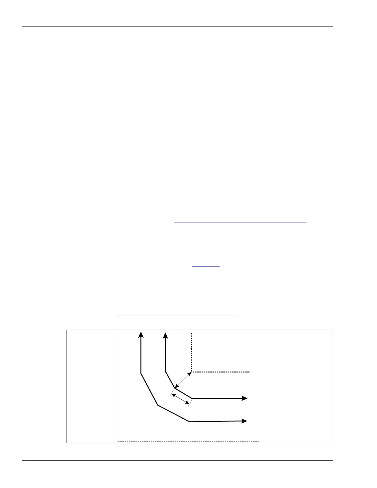
When installing cables in concrete, make turns by cutting the slots in a series of three short lengths
with 30º turn angles (for a 90º turn). The changes of direction should be separated by at least
3.6 m (12 ft.) (see Making gradual turns in concrete
on page 39). Keep the turn in as smooth an
arc as possible.
Figure 28: Sensor cable installed around corners in concrete slots
inner fence
1 m (3 ft., 3 in.)
minimum at closest point
3.6 m (12 ft.)
minimum between 30° turns
outer fence