Calibration
OmniTrax Product Guide Page 195
Following the Duty Cycle and Coding adjustment, select the Calculate button to determine the
recommended Transmitter Power setting.
Setting the initial configuration parameters
1. Under the View menu, select Advanced Parameters.
2. Select the Cable Common Cfig tab on the main UCM window.
3. Deselect (uncheck) the Accept Sync Signal check box (leave it blank) if this processor will be
the sync master; OR verify that the Accept Sync Signal check box is selected (checked) if
another connected processor will be the sync master and this processor will receive the
synchronization signal. (see Specifying the processor synchronization
on page 193).
4. Select the Side A Cfig tab.
5. Set the Cable Type - OC2, SC1/SC2, Sentrax (default = OC2)
6. Select the Cable Supervision Mode - clutter supervision, cable pair supervision, cable set
supervision (default = clutter supervision, see Sensor cable supervision on page 57
).
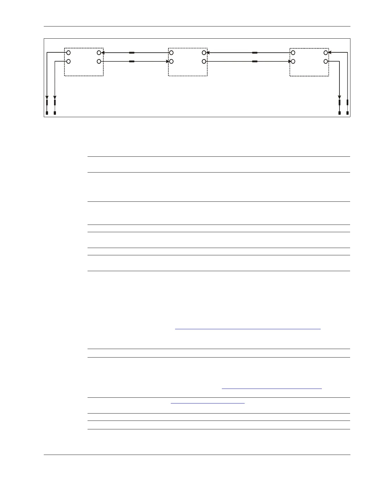
Figure 171: Transmitter coding
Note Senstar strongly recommends repeating the profile procedure if you
make changes to the Duty Cycle and Coding settings.
Note You must set the initial configuration parameters before calibrating the
OmniTrax sensor. If you make changes to these parameters after the
calibration is complete, you must repeat the calibration procedure.
Note If there is an unused cable side on a processor, you must deselect
(uncheck) the Enable check box for the unused cable side.
Note The initial configuration includes advanced parameter settings. You
may require a password to adjust the settings.
Note Each of the following steps must be repeated for Side B.
Note See Historic clutter
on page 217 for additional details on clutter
supervision.
Note For an unused cable side you must select clutter supervision.
OmniTrax processor #3
OmniTrax processor #2
OmniTrax processor #1
50% Duty Cycle
50% Duty Cycle
50% Duty Cycle
long terminators
long terminators
Accept Sync
Signal
Accept Sync
Signal
Sync master
1
1
2
2
2 1