Preparation of trenches
OmniTrax Product Guide Page 117
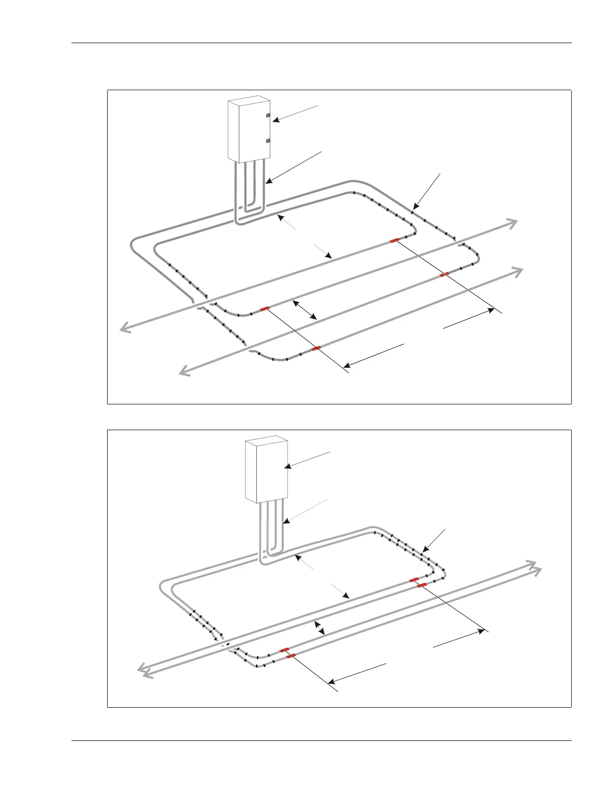
Start point configurations
Figure 82: OC2/SC2 sensor cable start point overlap (standard cable spacing)
Figure 83: OC2/SC2 sensor cable start point overlap (narrow cable spacing)
NOT TO SCALE
processor
enclosure
2 to 3 m (6.5 ft. to 10 ft.)
ferrite beads
(ten beads spaced 30 cm (1 ft.)
apart on each lead-in section,
beginning 30 cm away from
the red bands)
TXB
RXB
TXA
RXA
30 cm* (12 in.)
minimum
OC2/SC2 the red marks must line up on each cable set
* The 30 cm minimum separation between A-side and B-side active cables is critical to system performance.
lead-in section - minimum length of lead-in cable = 6 m (20 ft.)
8 m (26 ft.) detecting cable overlap
NOT TO SCALE
2 to 3 m (6.5 ft. to 10 ft.)
TXB
RXB
TXA
RXA
OC2/SC2 the red marks must line up on each cable set
* The 30 cm minimum separation between A-side and B-side active cables is critical to system performance.
6 m (20 ft.) lead-in section - minimum length of lead-in cable
8 m (26 ft.) detecting cable overlap
ferrite beads
3
0
c
m
*
(
1
2
i
n
.
)
m
i
n
.
processor
enclosure