OmniTrax components
OmniTrax Product Guide Page 17
connect the bulkhead connectors to the processor circuit card. Four cable glands on the
enclosure’s bottom provide access for the power cable, ground wire, alarm communication wiring
and the self-test or auxiliary device wiring.
The OmniTrax processor includes four output relays and two self-test/auxiliary inputs. A relay
output card (ROC) is available to provide eight additional outputs. For Silver Network based
processors, a universal input card (UIC) is available to increase the processor’s input capacity by
eight. A processor can use either an ROC or a UIC, but not both.
Each network based processor requires a Network Interface Card (NIC) which serves as the
communications interface to the Silver Network. There are five variants of the NIC, with each being
specific to the network media. EIA-422 copper wire connections are made on removable terminal
blocks, and ST connectors are used for single-mode and multi-mode fiber optic cable.
There are two selectable control modes for the OmniTrax processor’s relay outputs and AUX
(auxiliary) inputs. The control mode is set in software via the UCM. The default setting is local
control mode, in which the OmniTrax processor controls the relays to signal alarm and supervision
conditions, and the AUX inputs are self-test inputs. Using the optional ROC, you can configure up
to ten distinct alarm zones per processor for relay output alarm communications. For Silver
Network based processors, remote control mode enables the host SMS to operate the processor’s
relays, as output control points, and the AUX inputs function as auxiliary device inputs.
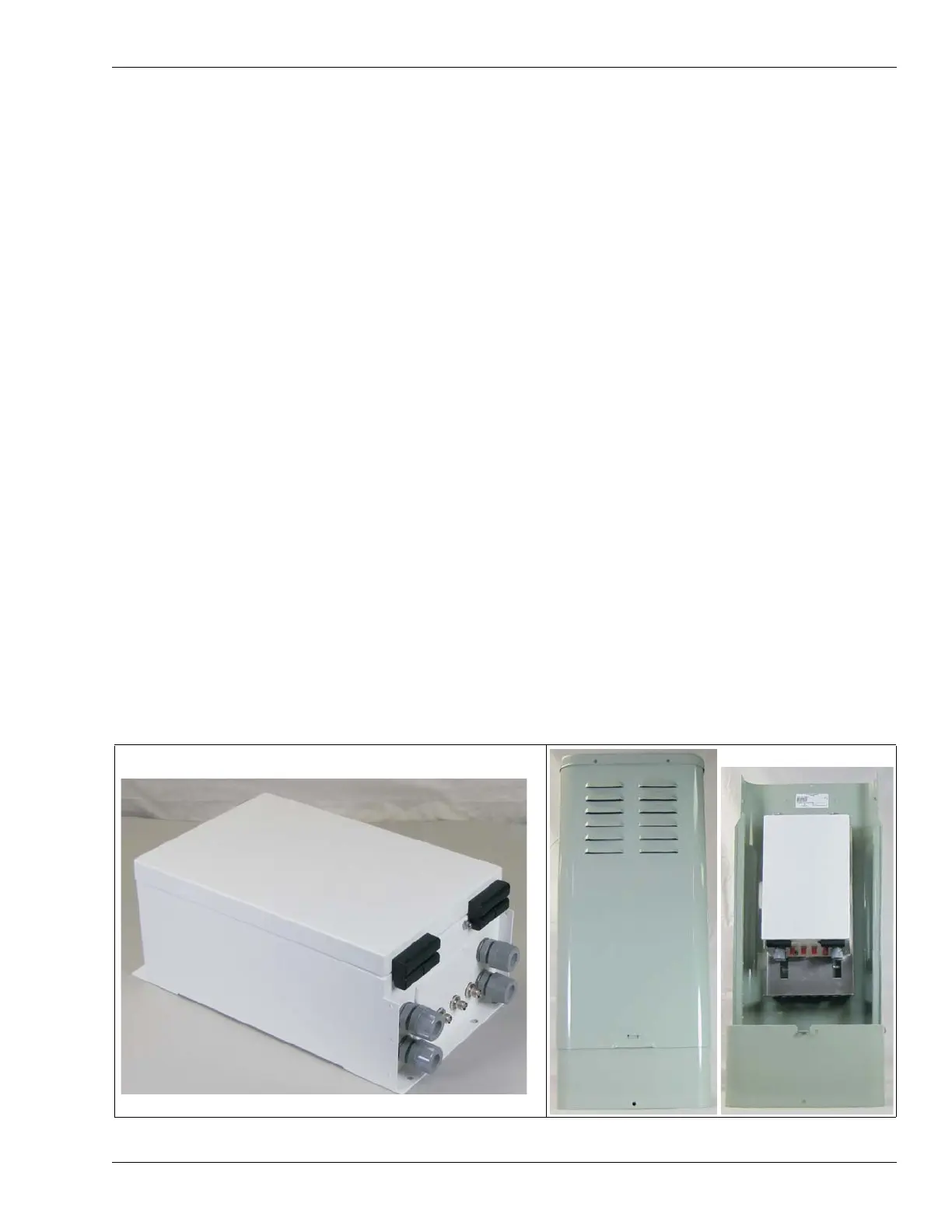
Enclosure
The weatherproof OmniTrax enclosure (IP66/NEMA 4) is painted aluminum and includes two
latches on the top for locking the door (locks not included) and hinges on the bottom to allow the
door to hang freely for easy access. There are two sets of mounting studs on the enclosure door,
one for the optional 6 VDC local backup battery and the other for the optional 12 VDC auxiliary
device power supply. The enclosure includes a vent to prevent gas build-up from battery charging.
An enclosure tamper switch is included with a harness that connects directly to the processor. For
outdoor installation, the OmniTrax enclosure must be installed inside a second enclosure to
protect the lead-in cables and the sensor cable connections. The two options for the second
enclosure are a telecom style enclosure, which is available from Senstar, or a Customer supplied
enclosure. The processor can also be mounted indoors in a secure area on a stable fixed surface.
Figure 2: OmniTrax weatherproof and telecom style enclosures