Setup
OmniTrax Product Guide Page 205
Cable margin procedure
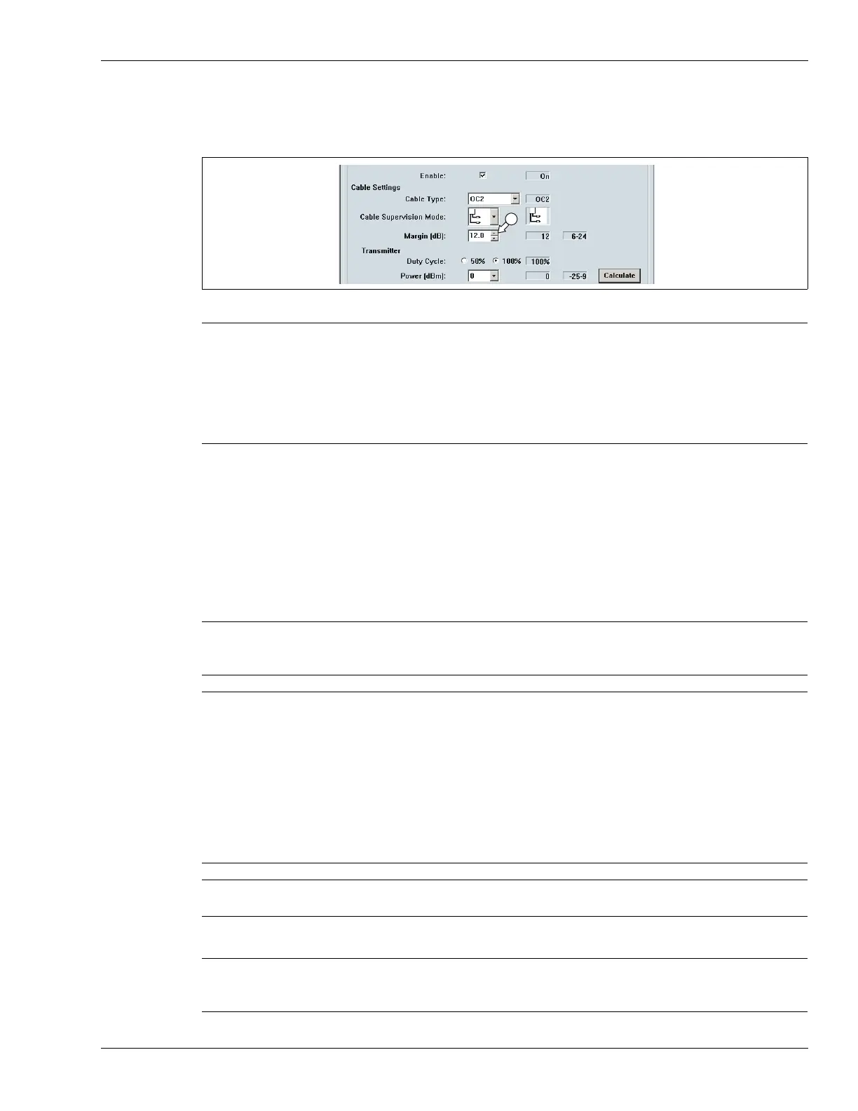
1. Use the spin control to set the cable margin for the full length of detecting cable.
2. Save the UCM file and download the configuration data to the processor.
Defining the cable segments and alarm zones
Each OmniTrax cable set can be divided into as many as 50 cable segments (100 per processor).
The defined cable segments can then be assigned to as many as 50 distinct alarm zones per
processor. In addition, there is Zone 0, which does not report alarms, and does not count in the 50
zone total. You define the detecting sensor cable as cable segments, according to your site-
specific requirements for alarm zone layouts. You can also adjust the cable margin independently
for each cable segment to raise, or lower, the alarm threshold in that area.
The following procedure is performed in the Segment Settings field of the Cable Cfig tab.
Figure 183: Setting the full length Cable Margin
Note At the minimum cable margin of 6 dB, the OmniTrax sensor will have a
reduced Pd, and an extremely low NAR/FAR. At the maximum setting of
24 dB, the system will have an extremely high Pd, but will be prone to
nuisance and false alarms from small animals, environmental effects
and background noise. The default setting of 12 dB provides a high Pd
and a low NAR/FAR. Senstar recommends the 12 dB default setting,
which can be adjusted, if required, as historical data is accumulated.
Note Senstar recommends that the lead-in cable be defined as segment 1.
The lead-in cable, and any detecting cable from which alarm reporting
is not desired, must be assigned to Zone 0.
Tip You can accurately locate cable segment boundaries by doing sensor
cable crossings.
Select File > Magnitude plot and set the OmniTrax response plot to
Absolute Display Mode and Peak Capture. Have the test subject walk
completely across the cable path at the desired cable segment
boundary. Note the position of the cursor for the first peak recorded.
Continue the crossings to mark all necessary segments (e.g., start point
of detecting cable, end of detecting cable, site specific alarm zones -
start and end of each zone). Refer to the response plot to define your
cable segments and alarm zones on the Cable configuration screen.
Note After calibrating your OmniTrax processor you will have one alarm zone
for the full length of detecting cable.
Note To precisely locate the segment boundaries, you can use the UCM’s
Range (m) spin control to enter the meter where a segment begins. You
can adjust only the start point of each segment using the Range control.