Setup
Page 204 OmniTrax Product Guide
Setup
Once your OmniTrax processor is calibrated, you can setup the system for:
• cable margin (alarm threshold)
• cable segments and alarm zones
• individual segment cable margins (zone specific alarm threshold)
• target speed (velocity response)
• input/output response
• network communication (for Silver Network based processors)
Setting the full-length cable margin
You can set the cable margin, thereby adjusting the alarm threshold for the full length of detecting
cable. The cable margin defines the number of decibels below the recorded sensitivity profile’s
peak response, that will trigger a sensor alarm. The sensitivity profile serves as the baseline for
the cable margin, enabling a consistent alarm threshold for each meter of detecting cable. The
cable margin follows the peaks and valleys of the sensitivity profile. By setting the cable margin
below the recorded sensitivity profile, your alarm threshold is always lower than the known
sensitivity of the cable. For example, if you use the default setting of 12 dB for the cable margin,
your alarm threshold is 12 dB below the cable’s peak reading. Whenever the processor detects a
target with a signal that is within 12 dB of the recorded sensitivity profile, an alarm is declared. A
cable margin of 12 will provide a high probability of detection (Pd) and a low nuisance alarm rate
(NAR).
Note The default settings for cable margin and target speeds provide good
detection for most installations. However, variations in cable spacing,
burial depth and soil conductivity affect the system’s performance from
site to site. After initial calibration, perform multiple crossing tests to
verify that the system meets your detection requirements.
Note The following procedures assume that the processor and sensor cables
are installed, the processor is powered up and calibrated, and the UCM
computer is in communication with the processor. Each procedure
references the A-side cable set. You must repeat each procedure for
the B-side cable set.
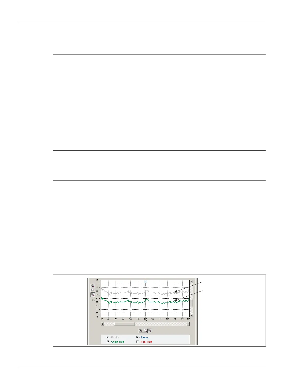
Figure 182: Cable margin
recorded sensitivity profile
cable margin set to 12 dB