Network communication
OmniTrax Product Guide Page 177
Relay ratings/settings
The dry contact relays are form C and are rated for 30 V @ 1 A max. In network control mode, you
can configure the relays as latching (steady ON), in flash mode (ON-OFF-ON-OFF, etc.), or pulse
mode (ON, then OFF). For flash and pulse modes, the Active/Inactive times are selectable.
AUX I/P specifications
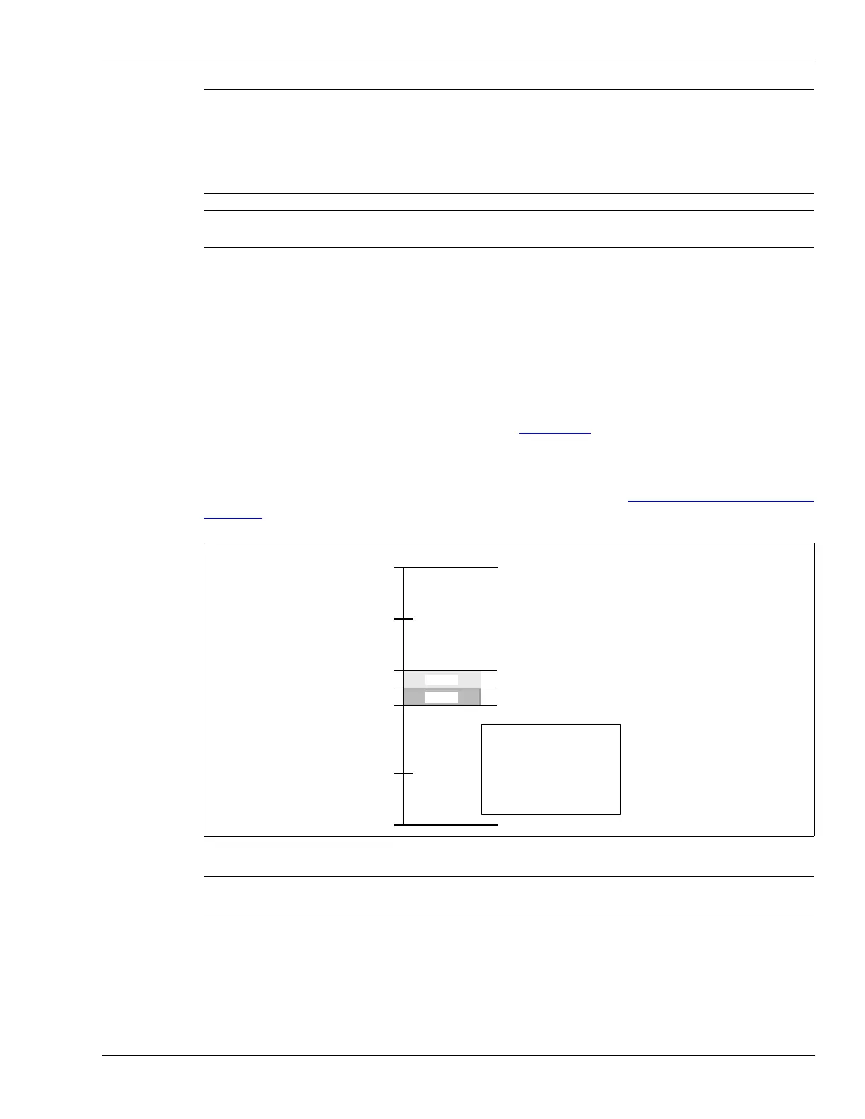
AUX 1 and AUX 2 are voltage sensing inputs (see Figure 155:). The processor determines an
input’s status via an internal reference voltage, and the configuration of the contact closures and
supervision resistors. In remote control mode, the AUX inputs (and UIC inputs) serve as auxiliary
device inputs to the host system. You define the inputs via the UCM, as NO or NC with single
resistor supervision, dual resistor supervision, or unsupervised (see Input wiring configurations on
page 212). The Filter Window parameter (via UCM) allows you to set the time period for which an
input must be active, before an event is reported.
Note Senstar strongly recommends the use of low capacitance shielded
twisted pair data cable for EIA-422 (e.g., Belden 9729),
62.5/125 multimode fiber optic cable, and
9/125 singlemode fiber optic cable. The maximum separation distances
require high quality transmission media and sound installation
practices.
Note To communicate over the Silver Network (and over the sensor cables) a
network interface card (NIC) must be installed on the expansion header.
Figure 155: Voltage sensing inputs
CAUTION Use 1%, 1/4 W supervision resistors for OmniTrax inputs.
Contact closure inputs MUST be voltage-free.
VDC
auxiliary inputs voltage range
tamper
alarm
secure
tamper
alarm threshold voltages
*
thresholds based on:
dual resistor supervision
NC alarm contact
R1 = 5.1 k, R2 = 820
40 mV noise tolerance
and 0 mV line drop
*